DIY variable speed grain mill

Homebrew Talk - Beer, Wine, Mead, & Cider Brewing Discussion Forum

Help Support Homebrew Talk - Beer, Wine, Mead, & Cider Brewing Discussion Forum:

This site may earn a commission from merchant affiliate links, including eBay, Amazon, and others.

ernestmyname

Well-Known Member
Joined
Mar 31, 2009
Messages
53
Reaction score
0
Location
Clemson, SC
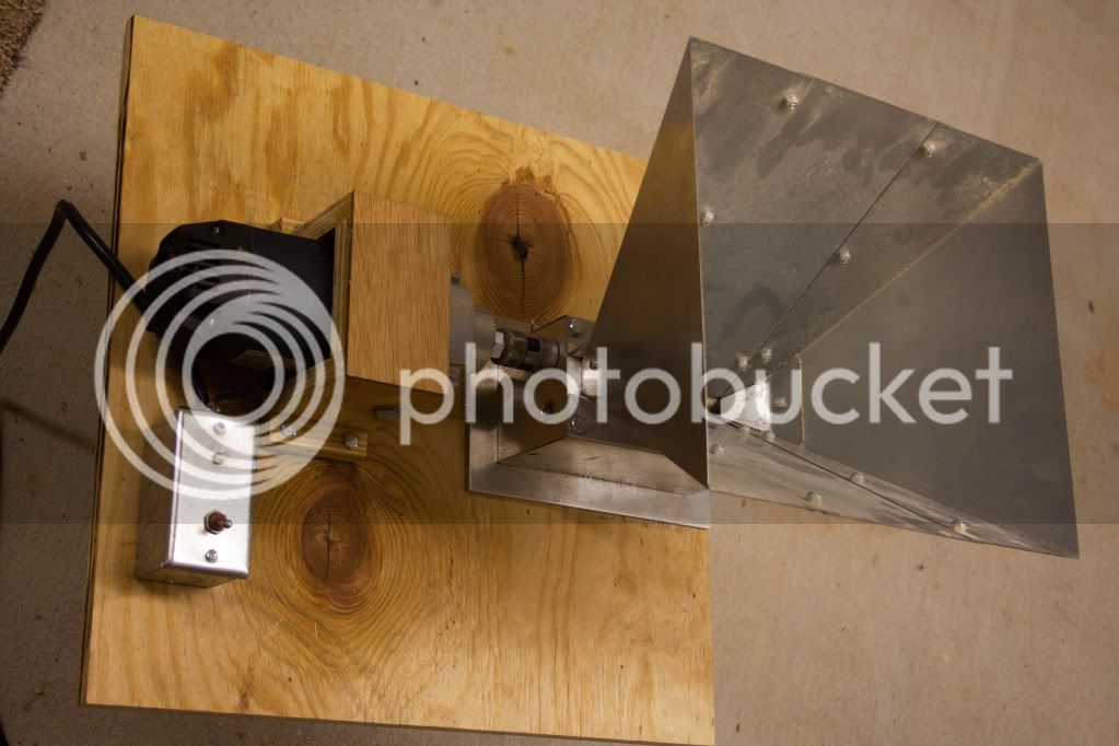
Yet another motorized grain mill. The speed of the mill is varied by a knob mounted on the box with the ON/OFF switch. Max speed is 550RPM. You can't see my hand operating the potentiometer but you can hear the speed changing quite clearly. Having learned some things, I would say i could do the same thing again for around 60usd (counting the cost of the drill). If I had parts lying around I could do it for much less. I can do a cost breakdown and a parts list if anyone is interested. There was quite a bit of modifying that took place. You don't necessarily have to start with a new circuit board although it sure made it easier once I came up with a circuit that worked well. The board in the drill itself is some type of ceramic that is nearly impossible to drill through and cracks very easily. This made modifying the existing circuit/PCB nearly impossible.

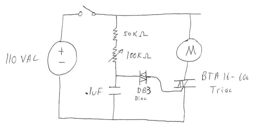
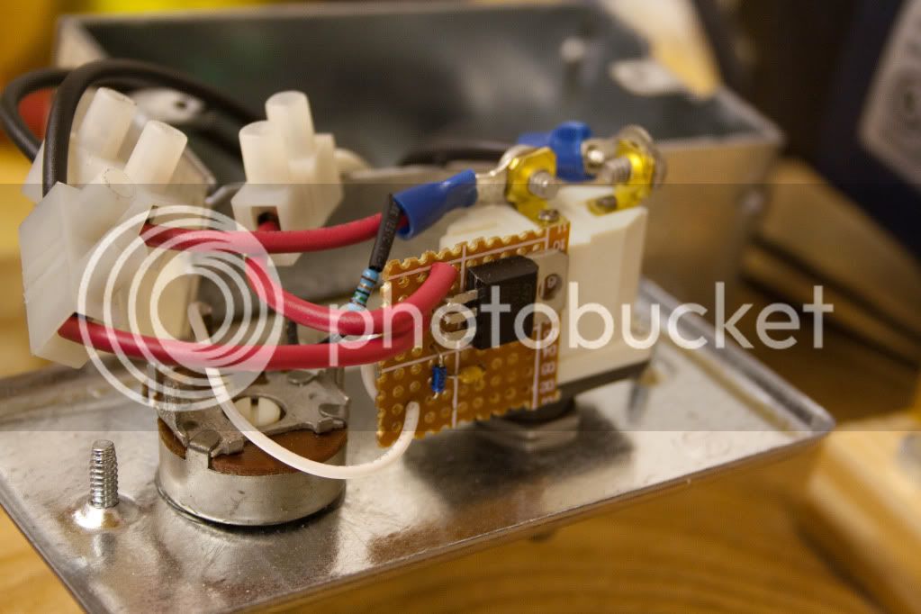
With the new parts, my circuit will support a drill up to 16A. Majorly overkill since the drill I'm using is plenty and it is only 7.5A

[ame=http://www.youtube.com/watch?v=RqAs--HDdrs]Motorized Monster Mill - YouTube[/ame]

IMG_9194.jpg


IMG_9242.jpg


IMG_9238.jpg


IMG_9240.jpg
 
I can't tell in the pic, but is that a PWM you've built? If not, can you give a little explanation?

Thanks

B
 
Looks like a simple AC Voltage Regulation circuit. The IC is a BTA16-600B and it looks like a couple of small capacitors. I am sure there schematics out on the interwebs.
 
This circuit has the same concept as PWM but you are using the sinusoid from the wall outlet to trigger the pulses. The pulses apply 110 volts to the motor windings. Varying the resistor varies the time that the ON pulse comes on in a single sinusoidal period.

The motor is a DC brushed motor that runs off of AC. Question 7 on this page has an illustration to show the internal workings of the motor:

DC motor theory : Worksheet

An SCR is the same device used in modern dimmer switches. A SCR coupled with a DIAC are commonly used as drivers for DC motors. That is all I have in my circuitry. You can read in greater detail here:

The Silicon-Controlled Rectifier (SCR) : THYRISTORS

That page is one of the many I referenced when I was coming up with a suitable replacement circuit when I accidentally destroyed the one that came with the drill.

There is a lot of information here that I am sure is quite vague. I can go into excruciating detail here but chose to leave it to the professionals (links).
 
Looks like a simple AC Voltage Regulation circuit. The IC is a BTA16-600B and it looks like a couple of small capacitors. I am sure there schematics out on the interwebs.

These circuits (a SCR with a DIAC) are very popular. There is a lot of information out on the nets on different flavors and varieties. I didn't post this intending for others to be able to replicate it through the pictures (especially considering there is no way to tell the DIAC isn't just a capacitor). I intended to jot a ckt down on paper and post it up if anyone was interested. I doubt my circuit is the best for this application although it seems to get the job done.
 
Is that a dremel? Or is it a drill with the handle through the table?
 
I like it! I'll have to show this to a friend who I built a mill for. He will surely be looking for a way to power it, and this is simple and effective, not to mention fairly cheap.
 
I cut the handle off the drill. I surely have some more photos around here somewhere.. The drill is this one here.. I got a coupon off the internet which brought the drill total down to ~ 35 usd.

1/2" Heavy Duty Low Speed Drill

You can see that there is already a spot on the side which makes it easy to bolt it to something. Plenty of torque. I have only put 15 or so lbs through the mill so far. The operating manual for the drill (if I remember correctly) says to not run it constantly for more than 6 or 7 minutes. That is the main limitation to this setup. If you are going to be grinding a ton of grain this definitely isn't the best approach. There seems to be some interest in my setup so I will try to get my circuit sketched out and in this thread in the next couple days.

[edit] I took this approach mainly because I didn't want pulleys, etc. which are much larger and seem to pose a finger risk unless the setup has bulky guards. I couldn't ever decide on a geared motor and the selection is quite small. A buddy in my engineering group mentioned using a permanently mounted drill and I ran with the idea. I'm eager to compare extraction rates with grain ground at different speeds. But that will be a while since I have a rather large brewing project I'm working on now. :D
 
The 1/2" chuck was way too long. I was going for compact so I took it off. I ground down the 1/2" threads coming out the drill to make it shorter and made a coupling with a 1/2" bolt which allowed me to attach a lovejoy coupling to the drill. I ground the head off the bolt and used the 1/2" unthreaded part to attach the lovejoy coupling. The threaded portion of bolt screwed half-way into a 1/2 inch nut. The drill screwed in half-way in the same nut.

IMG_9234.jpg


IMG_9231.jpg


IMG_9232.jpg
 
These circuits (a SCR with a DIAC) are very popular. There is a lot of information out on the nets on different flavors and varieties. I didn't post this intending for others to be able to replicate it through the pictures (especially considering there is no way to tell the DIAC isn't just a capacitor). I intended to jot a ckt down on paper and post it up if anyone was interested. I doubt my circuit is the best for this application although it seems to get the job done.

Thank you for enlightening me. I am by no means an EE and only have experience with DC circuits. I will be sure to read the links you posted, I am always down to learn something new.
 
Dude...Can you post the schematic?

CktAsRequested.jpg


I'm fairly sure this is it. I'm not 100% on the resistor value. I tried to read it from the pic I posted as I don't have the device with me at the moment. Those resistors have a different band scheme than I am accustomed to.

I am going to experiment with adding another (different style) diac in parallel with the capacitor. This seems common in circuits I have seen around the internet. Something to do with back EMF from the motor. But it will be a couple weeks before I get to do some testing. Happy Holidays!
 
Finally got a chance to brew today.. Ground 22lbs of grain with the mill and my only complaint is the noise. It is quite loud in an enclosed area. I like the speed adjustment a lot. I'm not sure why but I adjusted the speed a couple times during the crush. Sometimes it seemed to need a speed increase. Other times it seemed like it needed to slow down a bit. :D

I would be eager to know if anyone uses the information I have posted to do anything useful. I monitor my PMs so if anyone has any questions or needs any parts just ask.
 
ernestmyname said:
Finally got a chance to brew today.. Ground 22lbs of grain with the mill and my only complaint is the noise. It is quite loud in an enclosed area. I like the speed adjustment a lot. I'm not sure why but I adjusted the speed a couple times during the crush. Sometimes it seemed to need a speed increase. Other times it seemed like it needed to slow down a bit. :D

I would be eager to know if anyone uses the information I have posted to do anything useful. I monitor my PMs so if anyone has any questions or needs any parts just ask.

I believe that is a torque issue. I notice my drill doesn't have enough torque at lower rpms with a full hopper, but I have to slow it down when its almost finished
 
Back
Top