looking for wiring help

Homebrew Talk - Beer, Wine, Mead, & Cider Brewing Discussion Forum

Help Support Homebrew Talk - Beer, Wine, Mead, & Cider Brewing Discussion Forum:

This site may earn a commission from merchant affiliate links, including eBay, Amazon, and others.

bagpiperjosh

Well-Known Member
Joined
Jan 19, 2012
Messages
343
Reaction score
1
Location
Plum
i plan to do my eherms system with a 1 pid controller from auber ins, and one of these for the mash tun http://www.ebay.com/itm/250560351944

i would like to use the one pid controller to control the hlt and BK. does anyone have a wiring diagram how to hook up both temp probes to the one pid on a switch? ive been explained how it works, but i need a visual to fully grasp it.

thanks in advance

btw incase i wasn't clear. the hlt and bk will each have their own element. they will be on a on-off-on switch.
 
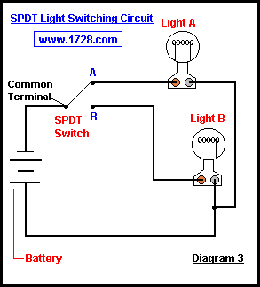
Sounds like you are talking about a Single Pole Double Throw Switch?
http://www.1728.org/project2.htm

Common terminal will be wired to the input of the PID, A will be wired to HLT, B will be wired to BK.
The probe wiring shouldn't be any different than the element wiring. Unless I am missing something?

Nope, need 3 poles. RTDs have 3 wires - 2 reds and a white if you get the Auber ones.
 
Nope, need 3 poles. RTDs have 3 wires - 2 reds and a white if you get the Auber ones.

Right; all you need to do is switch the white wire with a SPDT switch.
The reds can all land on the PID.

Here is how you switch a load using s SPDT; you should be able to switch the input the same way.

spdt.gif
 
Right; all you need to do is switch the white wire with a SPDT switch.
The reds can all land on the PID.

Here is how you switch a load using s SPDT; you should be able to switch the input the same way.

what about having to different temp sensors on the same pid? how would that be hooked up? because dont you pretty much need a temp sensor for the BK for it to work properly?
 
what about having to different temp sensors on the same pid? how would that be hooked up? because dont you pretty much need a temp sensor for the BK for it to work properly?

From what I’ve read, you only need a temp probe hooked up for the PID to work. So you can keep the temp probe hooked up in the HLT, and when it comes time to boil in the BK you just switch the PID to manual and you can throttle the power to a percentage that gives you a good rolling boil. In manual mode the temp probe does absolutely nothing as far as the temperature is concerned, but you need to have it connected for the PID to run. It sounds strange, but this is one of only a couple things I hear people complaining about the PIDs.
 
FWIW I ordered two temp probes from Auber thinking the same thing, that I needed one for the BK. My solution to justify my premature illicit purchase was to spend more money, and buy a separate temperature readout panel that I will wire the BK RTD to. This way I can monitor the temps as it approaches boil and also while cooling, but it doesn’t affect my control panel at all.
 
i would like to use the one pid controller to control the hlt and BK. does anyone have a wiring diagram how to hook up both temp probes to the one pid on a switch? ive been explained how it works, but i need a visual to fully grasp it.

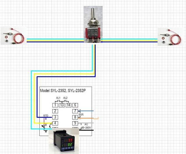
I might be misunderstanding the question, but I think all you are looking for is something like this 3PDT switch. Basically you wire the 3 wires from the PID into the center pins of this toggle switch. Then you wire each respective RTD probe on the left and right sides (just be sure to keep the reds and the whites in the right pins). Because this switch is small I used heat shrink with solder to secure all the wires to the pins and keep them from touching each other.

This allows you to toggle between the HLT and the BK for a temperature for each, when one or the other is in service. Only down side is the PID will only allow you to adjust for one probe. i.e. one probe might need a dp adjustment of 1F and the other 3F. You will have to note the difference and have only one probe accurate.

You don't need a probe for each kettle, but I like knowing when the BK is about to boil i.e. hot break time; and I use an IC so I like to know where I am at in the chilling process as well. This set up allows for that convenience.

3PDT.jpg
 
I might be misunderstanding the question, but I think all you are looking for is something like this 3PDT switch. Basically you wire the 3 wires from the PID into the center pins of this toggle switch. Then you wire each respective RTD probe on the left and right sides (just be sure to keep the reds and the whites in the right pins). Because this switch is small I used heat shrink with solder to secure all the wires to the pins and keep them from touching each other.

This allows you to toggle between the HLT and the BK for a temperature for each, when one or the other is in service. Only down side is the PID will only allow you to adjust for one probe. i.e. one probe might need a dp adjustment of 1F and the other 3F. You will have to note the difference and have only one probe accurate.

You don't need a probe for each kettle, but I like knowing when the BK is about to boil i.e. hot break time; and I use an IC so I like to know where I am at in the chilling process as well. This set up allows for that convenience.

yea, thats exactly what i was looking for. as long as i dont NEED a rtd in the Bk i may wait to add that though... thanks for everyones help
 
yea, thats exactly what i was looking for. as long as i dont NEED a rtd in the Bk i may wait to add that though... thanks for everyones help

Definitely not needed as long as you leave the probe on the HLT all the time.
 
FWIW, I think there is a way to run an element via a PID without any RTD.

If you short out terminal 4 and 5 with a copper wire and put the PID in the thermocouple setting (i think "0") it should display ambient air temp and run the element. I haven't tried this but I believe that this will work.

Personally I really like seeing the temps and love the rtd probes
 
Back
Top