Time sharing 2 elements with a 30 amp panel

Homebrew Talk - Beer, Wine, Mead, & Cider Brewing Discussion Forum

Help Support Homebrew Talk - Beer, Wine, Mead, & Cider Brewing Discussion Forum:

This site may earn a commission from merchant affiliate links, including eBay, Amazon, and others.

crane

Supporting Member
HBT Supporter
Joined
Sep 20, 2011
Messages
1,215
Reaction score
457
Location
San Diego
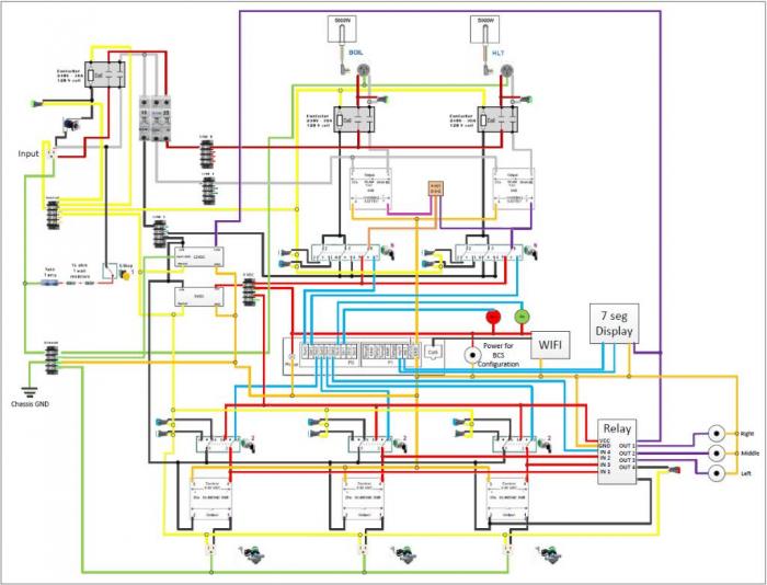
This topic has come up a few times and I have added my input as to how I would go about doing this. I recently built a new control panel and implemented this feature using a single P-FET transistor. My control panel is based around the BCS-460 but you could also do this same implementation if your panel uses multiple PID controllers. If you are using an arduino, BBB, R - pi or some other micro it could be implemented better with code.

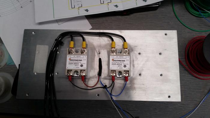
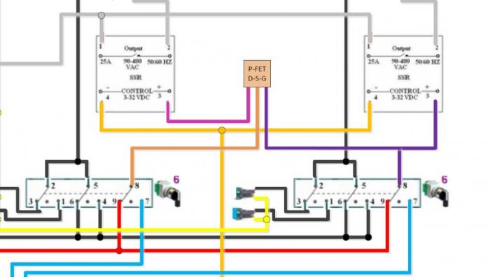
I brewed my first batch last Saturday and it worked quite well. My current system is a 2 vessel setup with a RIMS tube to control mash temps. I heat my strike and sparge water in my boil kettle. While I am mashing the RIMS duty cycle is pretty low because it doesn't need a lot of power to maintain mash temps. During this time the majority of the 1 second period can be used to heat my sparge water. Here is some pics of my wiring diagram of how to implemented this.

The D, G and S on the P-FET represent the drain, gate and source terminals. You could easily add a switch to change the priority. I may do this in the future so I can begin my cleaning cycle in the mash tun while I'm boiling. Currently the RIMS tube will always have priority over the boil kettle.
1402862424678.jpg


1402862441348.jpg
 
If I understand your schematic: you use the P-Fet to alternate the two associated SSRs. When one is SSR on, the other SSR is off.

If I understand it, you use a relay to turn the gate of the P-Fet on and off. What does the P-Fet do that the relay cannot do?
 
If I understand your schematic: you use the P-Fet to alternate the two associated SSRs. When one is SSR on, the other SSR is off.

If I understand it, you use a relay to turn the gate of the P-Fet on and off. What does the P-Fet do that the relay cannot do?

The first part is correct, the second is not. The gate of the FET is coming from a switch. In manual mode it supplies 5V to the gate. In auto mode it is connected to the HLT output of the BCS. The relays are on the output of the SSR and are on when the switch is in manual or auto mode.

You do not want to use a relay in place of the FET. The FET will last forever whereas a mechanical relay will die from the continuous switching from the PWM output of the BCS. Also the FET is much cheaper.

I thanks. I did not pick up that the FET was also doing PWM switching.

On a side note. I see something in designs that is counterintuitive to me. People put the SSR in series with a contactor. I get that. One is a robust On OFf switch the other is a PWM driver. If you have the money and space, excellent idea.

But why put the SSR before the contactor? Why subject the SSR to switching into a dead load? My gut says turn power on & off into the SSR, then switch power with PWM. Do not know why I think it makes a difference, but it makes sense to me.
 
I have been evaluating the Brucontrol platform this summer and am getting ready to convert my control panel over to run off of it instead of using a BCS anymore. I am looking to add more automation and controlling the element priority select from the Arduino will be necessary to achieve this. The attached picture shows the schematic necessary to implement this. The Arduino has 3 outputs; BK PWM element drive, HLT PWM element drive, and the priority select output. These are shown at the top of the circuit. The outputs of the circuit are the BK and HLT SSR inputs shown at the bottom of the circuit. The circuit uses 4 P channel FETs and one N channel FET, as well as several resistors. Any value in the 1-10K Ohm range will work. I'm using 4.7K Ohms to be specific.

It works as follows. Only one element can be on at a time. If both elements are trying to fire at the same time then the priority select output from the Arduino will determine which one fires. If select is 1 then the BK has priority. If select is 0 then the HLT has priority.

Surely I could have very easily written my brew day script in Brucontrol to do this for me. However, I do not feel this is the most robust way to do this. When it comes to failure prevention, I feel that it needs to be implemented as closely to the source of the failure as possible. Having a circuit in place right in front of the SSR inputs acheives this. I only need power to be on in the panel for it to be actively preventing both elements from firing. If I were to have done this with a script, the Arduino would have to be on and connected to Brucontrol and Brucontrol would have to be running the script that prevents both elements from being on at once. Not a KISS solution if you ask me.

The last picture is some eye candy. I started out by mocking everything up on a larger breadboard and moved things over to perf-board after finalizing the circuits. The very bottom is a piece of FR4 with din rail mounts on the bottom. On top of that is a 16 channel relay board with another FR4 base plate on top of that. The upper FR4 has on the right; Arduino mega with a screw terminal shield and an Ethernet shield on top of that. On the left I have 2 perf-boards. One for 6 channels of thermistor inputs. The second perf board has my element priority select circuitry as well as PWM transistors for speed control of my DC pumps. Final the breadboard in front has 3 green LEDs to represent the pump PWM drive control, 2 yellow LEDs for the heating elements, 1 red LED for an alarm output, and finally 2 push button inputs.

View attachment 1505839616185.jpg
 
If this works, huge kudos to you.

Best to always have series resistors on FET gates in case the VGSS is violated. If you don't, possible dead short between gate and source after the overcurrent. Ask me how I know :) Also useful for slowing down the turnon time, especially with big fets with large gate cap.

I think this time-sharing feature is much better handled digitally. Let a processor make the decisions. I have thought about it a lot. Sadly, I haven't given it the the effort. Much kudos to you, @crane, for promoting thought to action.
 
I've been using this circuit for 7+ years without any issues. These are low voltage, low current FETs driving the inputs to SSRs.

Neither the BCS nor Brucontrol support this digitally, so that's never been option.
 
Last edited:
Back
Top