need help wiring controller

Homebrew Talk - Beer, Wine, Mead, & Cider Brewing Discussion Forum

Help Support Homebrew Talk - Beer, Wine, Mead, & Cider Brewing Discussion Forum:

This site may earn a commission from merchant affiliate links, including eBay, Amazon, and others.

dogwolf

Active Member
Joined
Sep 7, 2011
Messages
32
Reaction score
1
Location
tracy
i am plannig on doing both gas and electric brewing on my mlt and i am not sure on how to wire up my pid ssr to the gas solenoid and the heating element but this is what i came up with.i know i need to add fuses not sure where or what amp if anybody could check for me . sorry about the drawing i know it sucks.:confused:

mlt wiring.jpg
 
Whoa!!! Where is your 12VDC Power Supply? If your pulling 110 from the wall you need a transformer to lower it to 12 volts for the gas solenoid. Your current setup will blow up the solenoid as sure as you plug it in. Take a bit more time and think about each circuit and draw them individually, this will help insure you don't make mistakes like you have drawn here.
Wheelchair Bob
PS- I just reread this and did not mean for it to sound candascending, please ask if you need help there are many very accomplished electrical folks who will be glad to help you and not let you waste money or get hurt.
Bob

hey this is why we post. if i use a 110vac solenoid that would do it for that right. but how about some fuses any thought on that. by the way bob you did not sound candasending just worried. since i dont have any electrical knowlege any and all help is taken with appreciation.
 
If you could write up exactly how you want the pump, heating element, and gas valve to behave when you flip the toggle switch to "on", I'm sure we can draw you up a wiring diagram. Also, list the operating voltages for the three devices. I'm fairly confident the pump is 110vac, but the control voltage for the SSR isn't obvious, and neither are the power and control for the gas valve.

Btw, forget the word "fuse" for now, because you're a long way from worrying about those. The word you probably want to keep in your head is "relay", because I'm pretty sure you're going to need one or two to make this work, and you may need a DC power supply as well...

Cheers!
 
I tthought this was a joke. everything in the diagram was set up to go kabooom, except for the pump. Go to auber instruments website and read the manual to any of their pid controllers. They include diagrams for commonly used setups. I suggest you research a bit more and learn as much as you can before you design / build a system. That way you won't have regrets later. what you think you might need today may be different tomorrow.
 
You don't have your PID shown in the diagram. Also you need to fully understand how SSRs work to wire it up correctly. Generally they use a low voltage DC signal for their input which normally would come from the output of your PID controller. The output of the SSR is a switch so you would wire up one side from your source (line from the GFCI) and the other side would go to the STDP switch to select the element or the gas valve. However it sounds like gas valves run on 12VDC so that part isn't going to work either.
 
grandequeso said:
I tthought this was a joke. everything in the diagram was set up to go kabooom, except for the pump. Go to auber instruments website and read the manual to any of their pid controllers. They include diagrams for commonly used setups. I suggest you research a bit more and learn as much as you can before you design / build a system. That way you won't have regrets later. what you think you might need today may be different tomorrow.

Actually the only thing that would go kaboom would be the SSR. The output of the SSR would be connecting up non-energized wires so the heating element and gas valve would have 0 volts across their terminals regardless of what position the switch on the output is at. This is assuming that the SSRs input is low voltage DC. If the SSR used 120VAC as its input then nothing would go kaboom. The element and gas valve would simply have their input terminals shorted together.
 
Dogwolf,
Draw up a diagram of what you have now and add the info on volts, amps and any other specs to each item, then thinkl in terms of getting power from the wall safely to each item in the correct voltage. Once you have drawn out the circuits, then you can look at adding fises to protect the system. Sice brewing uses water I treat the whole system as a wet area hazard and use a Spa GFCI panel for the initial power feed into the panel. That will protect you from a major shock or burn. Once you identify each circuit you will need a way to turn it on and off or to control the voltage up or down. I use SSR's since they allow me to use very low, safe levels of voltage to switch them on and off. A small to medium 12 VDC power supply is very inexpensive and will make your project much easier to safely wire and do exactly what you would like for it to do. The key here is to not get discouraged, and try to be as thorough as possible on what you need and want in your system. Adding extra items now is relatively simple, adding the same stuff later may not be so easy, so plan in advance for the system to evolve and grow if you can. Hope this helps, and as always if you need help just holler or you can PM me and I will try to help you out.
Bob
 
If you could write up exactly how you want the pump, heating element, and gas valve to behave when you flip the toggle switch to "on", I'm sure we can draw you up a wiring diagram. Also, list the operating voltages for the three devices. I'm fairly confident the pump is 110vac, but the control voltage for the SSR isn't obvious, and neither are the power and control for the gas valve.

Btw, forget the word "fuse" for now, because you're a long way from worrying about those. The word you probably want to keep in your head is "relay", because I'm pretty sure you're going to need one or two to make this work, and you may need a DC power supply as well...

Cheers!

ok let me start from the top 110vac from wall through a gfci cord to back of controll panel.each wire of gfci connected to a differant terminal block +,-,ground. the pump and gas solenoid and heat element would each have a plug to plug into a wall type outlet installed in controll box powered by gfci cord.the jumper on outlets would be removed making each socket having to be wired separately.all would be 110vac. i would wire the pump by putting - to the - side of socket the + to a toggle(spst) switch to + side of socket. so i could turn on & off the pump. the pid would get - to its - side from the - terminal block the + would get + from the on side of pump toggle switch.so i cant turn on pid with out the pump running. out put on pid for gas valve - from - side of pid to - side of socket +side of pid to a spdt(on-off-on)toggle swtich to + side of socket.so i can toggle between gas and electric. for the heat element - from - side pid to 25a ssr + from 2nd post of spdt toggle switch to ssr. out put side of ssr - side to socket the + side of ssr to + side of socket.by the way i did mess up on saying gsv was 12vdc its 110vac my bad.the heating element is a 240vac 6000 watt element but since im running 110vac thats fine and makes it 1500 watt.the pid from aubers model syl-2342 says it has a built in relay. i hope this is a little better to understand if not please let me know im trying my best not to f up. thanks for all the help i really mean it. joe
 
To run an electric heating element with an SSR you are going to want the SYL-2352 and use the 12VDC output to go to the input of the SSR. The SSR is not going to directly power the heating element, meaning you can't connect the + on the output to the + on the heating element and the - on the SSR output to the - on the element. The - on the element comes directly from the - on the GFCI cord. The + on the GFCI cord goes to one side of the output on the SSR and the other side of the output on the SSR goes to the + on the element.

Think of an SSR as a SPST switch but instead of physically turning the switch to connect the two output terminals you apply a voltage across the two input terminals to connect the two output terminals. The input voltage doesn't actually get sent to the output. In fact the input side is optically isolated from the output so no electricity can flow from either of the input terminals to either of the output terminals.

so than there is no - off the ssr to element just from gfci cord and if its 12vdc output from pid i should use 12vdc solenoid for gas?the pid than just closes circut on ssr to turn on element?would the + from gfci go to input side of ssr than output side to element? once again thanks for all the help im starting to understand. joe:mug:
 
Dogwolf,
Draw up a diagram of what you have now and add the info on volts, amps and any other specs to each item, then thinkl in terms of getting power from the wall safely to each item in the correct voltage. Once you have drawn out the circuits, then you can look at adding fises to protect the system. Sice brewing uses water I treat the whole system as a wet area hazard and use a Spa GFCI panel for the initial power feed into the panel. That will protect you from a major shock or burn. Once you identify each circuit you will need a way to turn it on and off or to control the voltage up or down. I use SSR's since they allow me to use very low, safe levels of voltage to switch them on and off. A small to medium 12 VDC power supply is very inexpensive and will make your project much easier to safely wire and do exactly what you would like for it to do. The key here is to not get discouraged, and try to be as thorough as possible on what you need and want in your system. Adding extra items now is relatively simple, adding the same stuff later may not be so easy, so plan in advance for the system to evolve and grow if you can. Hope this helps, and as always if you need help just holler or you can PM me and I will try to help you out.
Bob

hey bob thanks for input im not ignoring you but im dealing with crane and he is being really helpfull if i still need help i will look you up. joe:mug:
 
At this point I think you should try updating your wiring diagram and posting it on here so we can review it. It is a lot easier to look at a schematic than it is to read through text describing it. Use as much detail as possible including PNs and pin numbers on devices. Use separate colors for wires of different voltages.
 
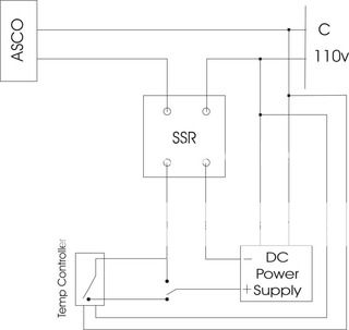
I drew this up for someone else a while ago, maybe it will help...

This is for a 110v valve, for a 12vdc (recommended) get rid of the SSR and wire the valve in its place.

ASCOSchematic.jpg
 
DW,
Crane is also one of the members who I am mentored by too. He has a very level head and explains stuff so even I can understand the reason behind some of the stuff electronics does. I don't think you could have gotten a better mentor. Good luck, and have fun with your build.
Wheelchair Bob
 
At this point I think you should try updating your wiring diagram and posting it on here so we can review it. It is a lot easier to look at a schematic than it is to read through text describing it. Use as much detail as possible including PNs and pin numbers on devices. Use separate colors for wires of different voltages.

i will try my best to draw a diagram(but i suck).i did how ever reallize what you were saying about how to wire it all up. i know how the pump is wired and the pid to. the 12vdc wires coming out of pid to input side ssr are easy now.what i got from you last night was the ssr is a spst switch and putting the + 110vac on only one side(+ input side of ssr) is how the power will go through the ssr and not fry the ssr with - going strait to heat element.on output + side of ssr goes to + side of heat element that hit me like a ton of bricks.with that said i know i can wire it up safely minus where to put fuses but im still working on it. once again thanks for all your help. joe:D
 
Rbeckett said:
DW,
Crane is also one of the members who I am mentored by too. He has a very level head and explains stuff so even I can understand the reason behind some of the stuff electronics does. I don't think you could have gotten a better mentor. Good luck, and have fun with your build.
Wheelchair Bob

Thank you very much for the compliment. I too have learned a lot from this forum and am glad to give back to the community with what I specialize in. I am glad that at least some of you out there appreciate what I can offer. It has also fun to see you learn on here and start to offer advice yourself WCB.
 
dogwolf said:
i will try my best to draw a diagram(but i suck).i did how ever reallize what you were saying about how to wire it all up. i know how the pump is wired and the pid to. the 12vdc wires coming out of pid to input side ssr are easy now.what i got from you last night was the ssr is a spst switch and putting the + 110vac on only one side(+ input side of ssr) is how the power will go through the ssr and not fry the ssr with - going strait to heat element.on output + side of ssr goes to + side of heat element that hit me like a ton of bricks.with that said i know i can wire it up safely minus where to put fuses but im still working on it. once again thanks for all your help. joe:D

Well the good thing about drawing a wiring diagram is that you can't get electrocuted when you don't hook things up right on paper. By trying drawing this up yourself you will think more critically and question what's going on rather than if someone provides the answer for you. In the end you will have a better understanding of what's going on. I am a firm believer that when it comes to high voltage electronics that you really need to have a good understanding of what each component does and how it needs to be hooked up.
 
Well the good thing about drawing a wiring diagram is that you can't get electrocuted when you don't hook things up right on paper. By trying drawing this up yourself you will think more critically and question what's going on rather than if someone provides the answer for you. In the end you will have a better understanding of what's going on. I am a firm believer that when it comes to high voltage electronics that you really need to have a good understanding of what each component does and how it needs to be hooked up.

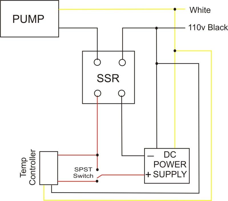
i agree and i am trying to draw this up still(but i suck) hopefully you dont laugh to hard at this.

new mlt drawing.jpg
 
DW,
Crane is also one of the members who I am mentored by too. He has a very level head and explains stuff so even I can understand the reason behind some of the stuff electronics does. I don't think you could have gotten a better mentor. Good luck, and have fun with your build.
Wheelchair Bob

you are right about him making it easy to understand i know i got it this time minus the fuses.but im still working on it. joe :ban:
 
dogwolf said:
i agree and i am trying to draw this up still(but i suck) hopefully you dont laugh to hard at this.

There is no reason for anyone to laugh, all this stuff is new to you. You got most of the way there except for how you are hooking up the SSR. You need to move the 120VAC from the input + terminal over to the one unused output terminal. SSR's are a little confusing when they label the output switch sides with + and -. There really is no polarity on the output side, meaning that you could reverse the element and line input connection and it wouldn't make a difference due to the fact that you are running AC through it. Basically you need to follow a rule of thumb in that the low voltage control signals go to the smaller input terminals and the high voltage wires go to the larger output terminals. That is assuming that they have different sized terminals like the SSRs I have used.

If you were to hook it up like you have shown you would likely blow the SSR and the PID. This is because you would be sending 120VAC into the output of the PID. When the PID goes to turn on its output it will now have 120V flowing back into its internal 12V bus. Most likely the microcontroller in there runs off of 3.3V or 5V and has a step down power supply from the 12V bus. Once 120V is applied to the input of that step down converter it will release the magic smoke and now you would have a dead PID. As for the SSR, it's input side turns on an optical isolator. The optical isolator has an LED on the input side and another photo activated semiconductor device on the output. When 12VDC is applied to the input the LED turns on. The light from the LED causes the output side of the isolator to turn on as well which turns on the rest on the output switch to effectively cause the output terminals to be shorted together. If you were to apply 120V to the input side you would most likely blow the LED in the optical isolator and your SSR would be dead. This last paragraph is a lot to digest but I thought I might give a little explanation as to what exactly would go wrong if you we're to hook it up this way.

you wont believe it but today i was at aubers and looked up how to connect pid ssr to heater there terminal 7-8 are outputs which go to 3-4 on ssr.#1 on ssr is input form 110vac. #2 is output form 110vac on ssr to heater.i now know how the ssr work:D but i didnt have a clue with out your help and doing all this searching.on the ssr i looked at #3was input + #4 was input - form pid. #1and #2where output.#1 will get 110vac form cord #2 will go to heater i will do another diagram correctly and post soon. once again thanks for all your help you are the man.joe

new mlt drawing.jpg
 
Awesome. Your diagram is correct now. To add a fuse just put it inline on the + line before the SPST switch going to the PID.

One word of advice when you go to build this. I recommend using a multimeter to ohm out all of your connections at the terminals to make sure that everything is securely connected and that you don't have any shorts between adjacent terminals. Also if you crimp ring terminals onto your wires for the SSR make sure that you have a really good solid connection by trying to pull it off the wire. I have had so many problems with using a regular pliers to make a crimp connection. You think its on there nice and solid and then you pull it off without any force. I finally went out and bought one of those combo crimper/wire strippers last year when I built up my box and it was worth the money. Every crimp connection was secure. You can never be too careful when it comes to high voltages.

alright i got it. :D once again thanks for all the help. i tip my hat and raise my glass to you. i couldnt have done without your help cant wait to build my box now.when i do i will post pictures and give you full credit on the wiring.joe
 
Back
Top