You are using an out of date browser. It may not display this or other websites correctly.
You should upgrade or use an alternative browser.
You should upgrade or use an alternative browser.
Need help with my electrical diagram!!!
- Thread starter Gabrew
- Start date

Help Support Homebrew Talk - Beer, Wine, Mead, & Cider Brewing Discussion Forum:
This site may earn a commission from merchant affiliate
links, including eBay, Amazon, and others.
Looks like good progress!

I just brewed my second batch today (10 gal this time), and you will love electric brewing! Looks like you'll be brewing before too long!
TB
I just brewed my second batch today (10 gal this time), and you will love electric brewing! Looks like you'll be brewing before too long!
TB
Are you fabricating your own panel? What are you using?
Good luck!
TB
Good luck!
TB
That's what I did (you probably knew that). It was easy to cut with an angle grinder, but rigid enough to use as a panel for my components. I didn't paint mine, but you might consider that option.
Keep the pictures coming!
TB
Keep the pictures coming!
TB
- Joined
- Nov 18, 2008
- Messages
- 2,058
- Reaction score
- 25
some updates:
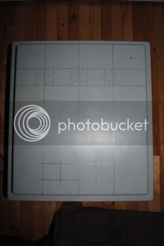
planning front pannel:
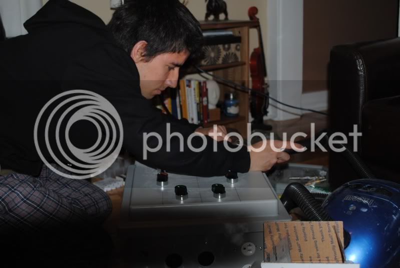
me wishing I had a garage...or at least a workbench:
Front panel before paint:
Bottom panel before paint:
Looking good.
ScubaSteve
Well-Known Member
- Joined
- May 21, 2007
- Messages
- 3,673
- Reaction score
- 91
Thanks TB
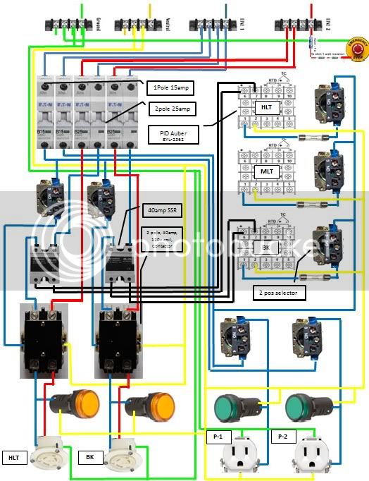
So heres an update with what Ive learned (thanks to you guys). Please let me know what you think!!!
Gabrew
Question....in this pic you show your element selector switch (previously a 3 position) as 2 separate 2 position switches. Why?
ScubaSteve
Well-Known Member
- Joined
- May 21, 2007
- Messages
- 3,673
- Reaction score
- 91
Duh....sorry...didn't see that you eventually went with the ability to use both ")
Quick Update:
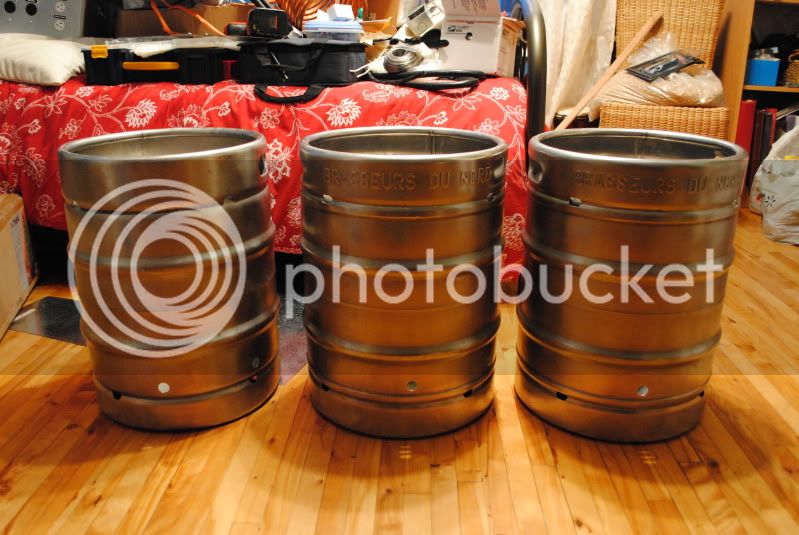
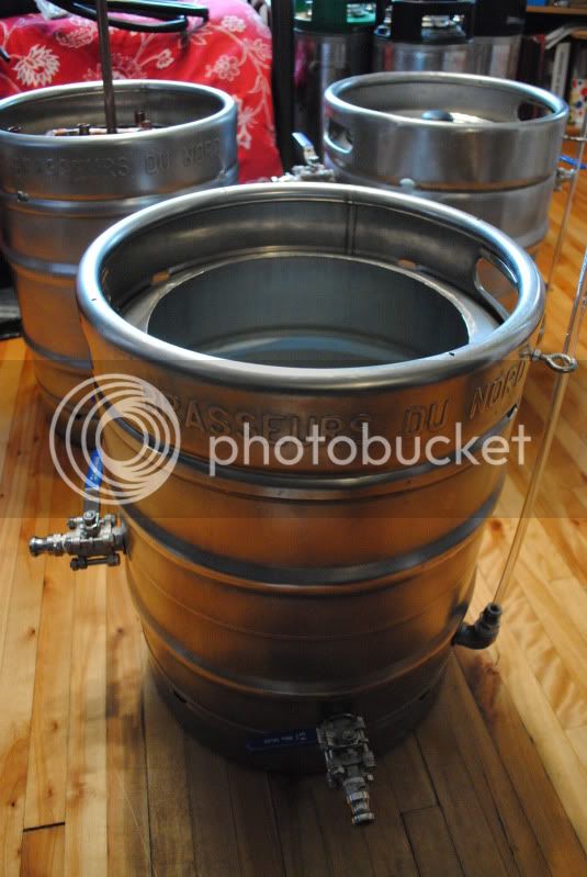
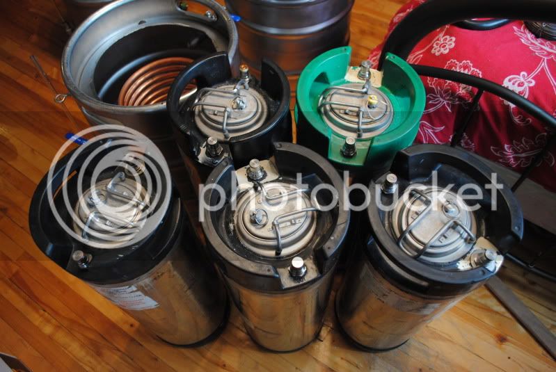
Just a quick polish of the kegs, they look a lot better than they used to. The plan was to get this brushed look and not a mirror finish...dont mind the mess
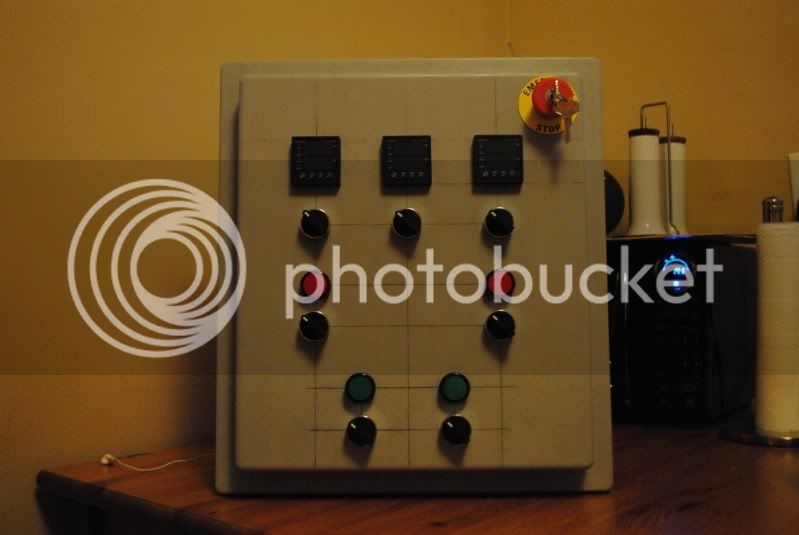
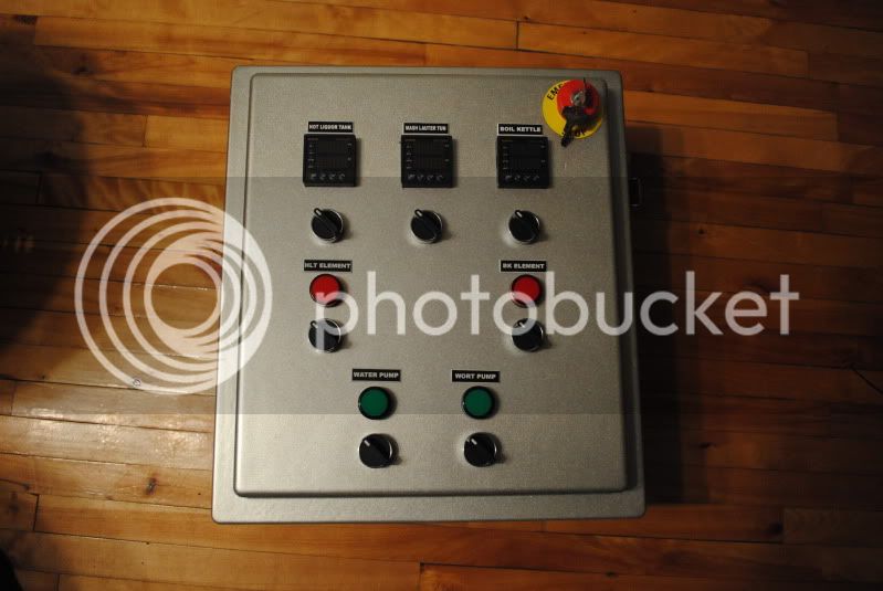
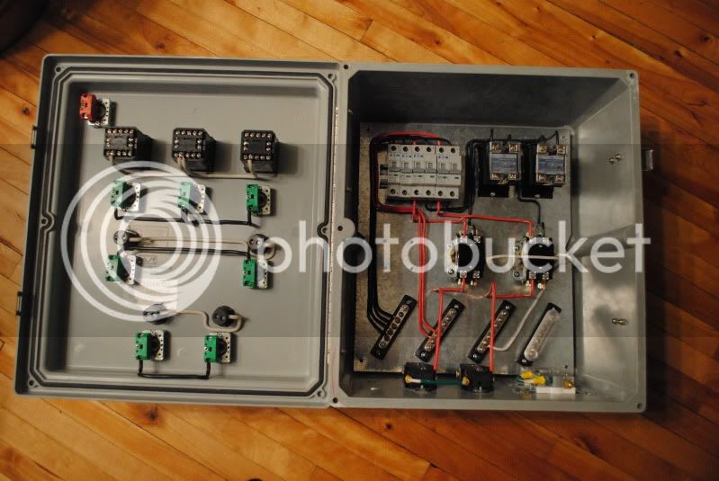
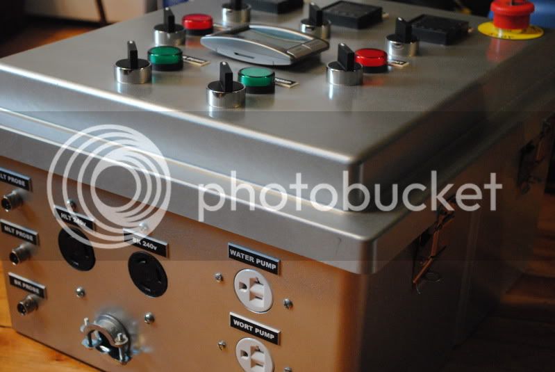
Here is the front panel. Pretty much done, I ordered this cheap timer which I may add to the center depending on its size. Not my first choice for paint color but it will do the trick
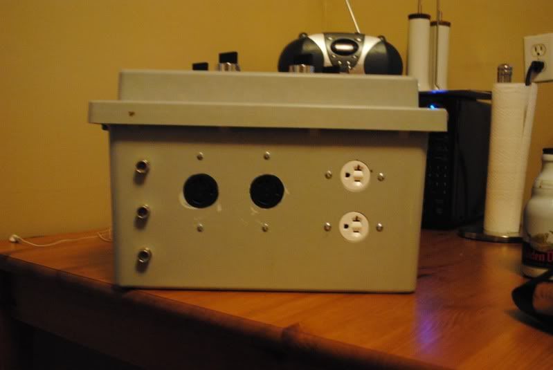
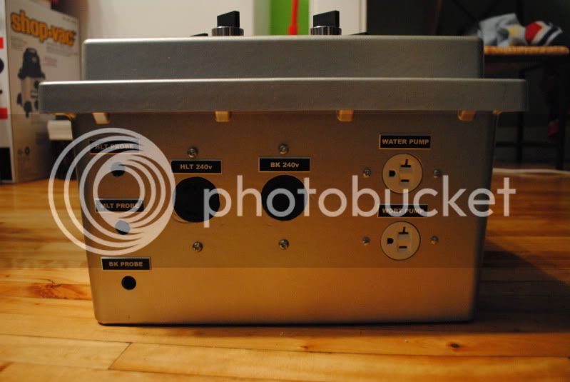
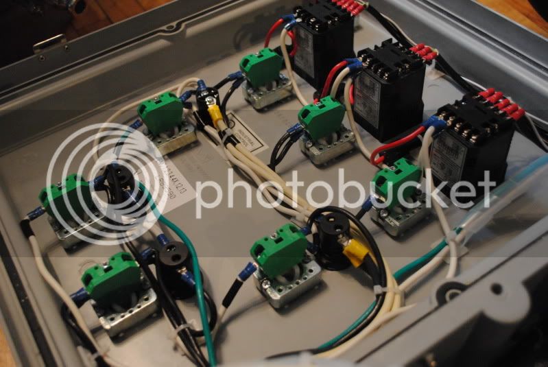
Bottom panel. Missing the temperature probe quick disconnects as well as the exit for the main power.
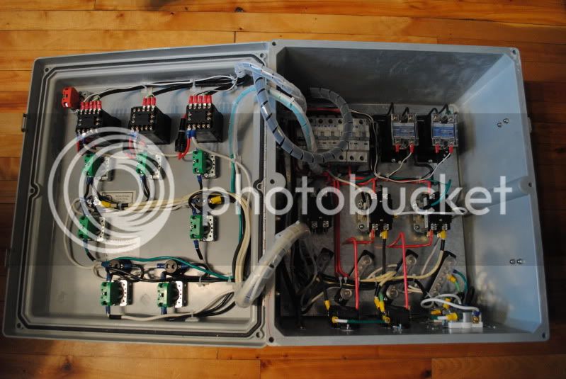
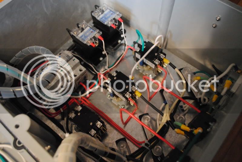
Some of the wiring done. Still waiting on a third contactor for the emergency push-button. Once received, ill begin wiring from the front to the back panel.
let me know what you think!
Gabrew
Just a quick polish of the kegs, they look a lot better than they used to. The plan was to get this brushed look and not a mirror finish...dont mind the mess
Here is the front panel. Pretty much done, I ordered this cheap timer which I may add to the center depending on its size. Not my first choice for paint color but it will do the trick
Bottom panel. Missing the temperature probe quick disconnects as well as the exit for the main power.
Some of the wiring done. Still waiting on a third contactor for the emergency push-button. Once received, ill begin wiring from the front to the back panel.
let me know what you think!
Gabrew
ScubaSteve
Well-Known Member
- Joined
- May 21, 2007
- Messages
- 3,673
- Reaction score
- 91
Looking great! That's going to be a really clean build....do the wires sit just like that, or did you affix them somehow?
Which timer did you go with? Was it one of the Ebay ones?
Which timer did you go with? Was it one of the Ebay ones?
Looks like you're making good progress!
You're not using solid wire for your enclosure wiring, are you??
Hope the rest of the build goes well!
Cheers,
TB
You're not using solid wire for your enclosure wiring, are you??
Hope the rest of the build goes well!
Cheers,
TB
Thanks for the comment!
The wires do hold by themselves, I had some solid 12 and 10 guage wire sitting at home, so they work great!
The timer is from ebay, payed under 10$ for it and should do the trick. I plan on installing a metal plate since the timer has both a clip and a magnet at the back. Thus allowing me to either install it to the control panel or bring it along if I have other things to do...
Everything looks great, except I would advise against using solid wire. I tried using solid wire in a few places, and then after a couple of times opening and closing the enclosure lid, the wire broke where the insulation was stripped. Luckily, that was during the period when I was wiring the box, so I was able to easily replace the solid wire with stranded wire.
I would recommend using stranded wire, and securing it with zip ties and/or spiral cable wrap, at least for the wire that's connecting the panel components to the inside components (where the wire will see some movement from opening/closing door).
Looks very clean, though, keep up the good work!
TB
I would recommend using stranded wire, and securing it with zip ties and/or spiral cable wrap, at least for the wire that's connecting the panel components to the inside components (where the wire will see some movement from opening/closing door).
Looks very clean, though, keep up the good work!
TB
so if i use stranded wiring for what connects the front panel to the back, I should be ok with what I currently got installed?
I think so. I'm still skeptical of the solid wire, but that might just be me. I would say at the very least use stranded for the wire that connects the front to the inside components. Basically, anything that sees any movement you'll want to use stranded.
TB
By the way, nice touch with the kegs. Looks a lot better than the mirror finish some of those guys are getting, IMO.
TB
TB
time for another update:
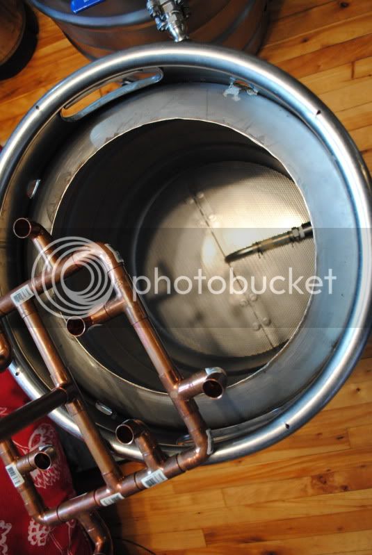
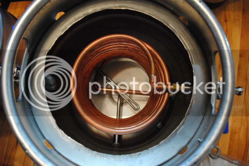
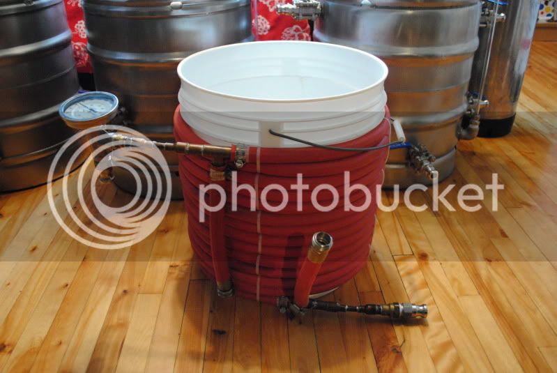
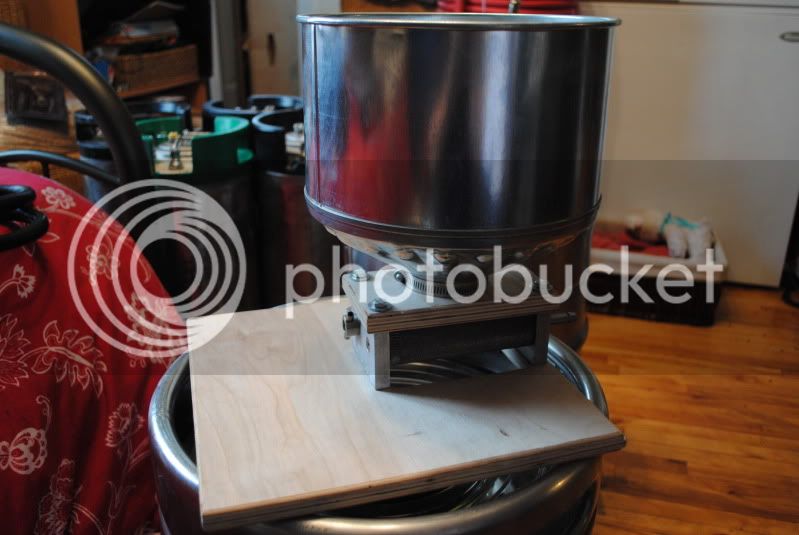
This weekend was rather productive, I finally got to install all the weldless fittings which showed to be rather effective as no leaks were found during my water test (good news!!!).
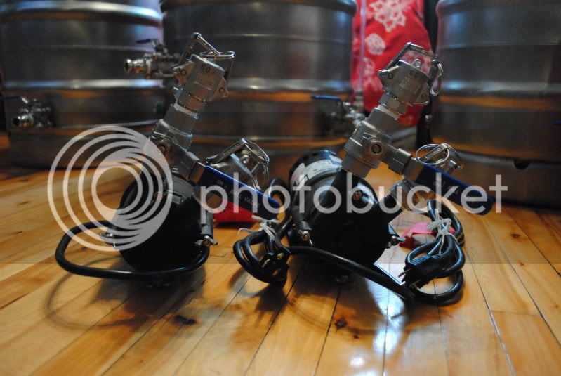
Some of the hardware:
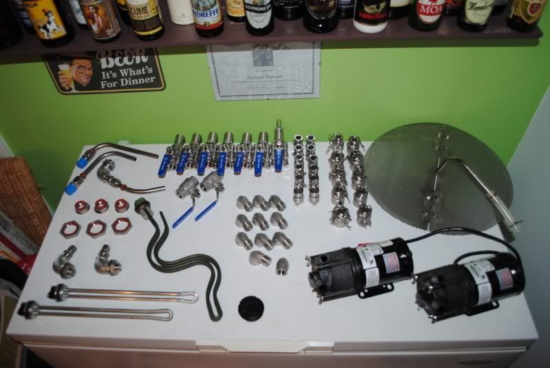
This weekend was rather productive, I finally got to install all the weldless fittings which showed to be rather effective as no leaks were found during my water test (good news!!!).
Some of the hardware:
Looks good! How'd you end up attaching your elements?
TB
TB
To do list:
-fix junction boxes to keggles and wire elements (need to find a way to order from mcmaster, they dont ship to canada and are not willing to ship to a us-based shipping center knowing that it will en up in Canada, they refuse to complete the transaction)
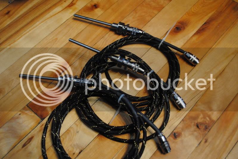
-Install rtds to keggles (same situation as above)
-Order and install 50amp gfi breaker...etc
-fix junction boxes to keggles and wire elements (need to find a way to order from mcmaster, they dont ship to canada and are not willing to ship to a us-based shipping center knowing that it will en up in Canada, they refuse to complete the transaction)
-Install rtds to keggles (same situation as above)
-Order and install 50amp gfi breaker...etc
Looks good! How'd you end up attaching your elements?
TB
Thanks!
Im planning on cutting a hole larger than the element and permenantly attaching the box onto the keggle using WB weld. It will allow me to protect the element while allowing easy change and keeping things weldless. I believe that Kals approach would not work due to the keggle wall thickness.
I'm having trouble imagining how you'd seal the element/keg mechanics from leaking...Thanks!
Im planning on cutting a hole larger than the element and permenantly attaching the box onto the keggle using WB weld. It will allow me to protect the element while allowing easy change and keeping things weldless.
I believe that Kals approach would not work due to the keggle wall thickness.
You are right. You could do it the way I did it, only soldering the locknut to the keg instead of welding if you don't have access to a TIG. It's easily disassembled for replacing parts, and holds a tight seal with no silicone or sealing compounds.
TB
I'm having trouble imagining how you'd seal the element/keg mechanics from leaking...
You are right. You could do it the way I did it, only soldering the locknut to the keg instead of welding if you don't have access to a TIG. It's easily disassembled for replacing parts, and holds a tight seal with no silicone or sealing compounds.
TB
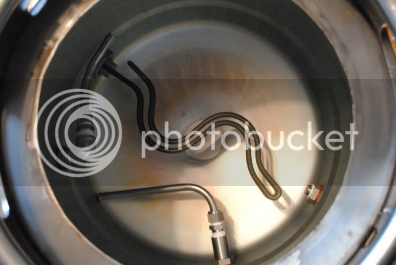
well the element itself is attatched to the keg only using a 1'' SS locknut with the elements original seal on the outside. This showed to prevent leaking in both kegs. as for the box, I was thinking of something similar to this (see post #4) using an aluminum 1 gang red dot box.
http://www.brewboard.com/index.php?showtopic=89493&mode=linearplus
I see, that should be fine. How are you going to ground it?
as you did, its the same box you have used only that its 1 isntead of 2 gang. Ive decided to not use the plastic box Ive showed before. The only problem is that I cant find the 3/4 NPT cord grips as well as some other stuff anyways except McMaster, and they dont ship to canada...so Ive got to find some other place to put the finishing touches on the system and finally get a brew going!
thanks!
Ive juste checked in with mcmaster and they finally agreed to ship my roder to a us-based shipping center!!! So, this means I should be able to get this thing completely done in a week or so. Cant wait!!!!
Ive juste checked in with mcmaster and they finally agreed to ship my roder to a us-based shipping center!!! So, this means I should be able to get this thing completely done in a week or so. Cant wait!!!!
That's good. I don't know how I would've finished my build without McMaster-Carr.
Thought about any first brew recipes?
TB
Thought about any first brew recipes?
TB
Gabrew,
Great looking build can't wait to see it all placed together and ready to operate...I love the way everyone on here helps each other out to teach us slackers and learn from the trend setting pioneers such as those who have paved the way for the rest of us to follow...Kal, Tiber Brew, Ohio ED, Scuba Steve, PJ and yourself...I am looking forward to start the equipment list requirements for my own e-HERMS, and begin the procurement of items for the build, and then let the fun begin....keep us posted on the progress!!! Thanks all the best
Great looking build can't wait to see it all placed together and ready to operate...I love the way everyone on here helps each other out to teach us slackers and learn from the trend setting pioneers such as those who have paved the way for the rest of us to follow...Kal, Tiber Brew, Ohio ED, Scuba Steve, PJ and yourself...I am looking forward to start the equipment list requirements for my own e-HERMS, and begin the procurement of items for the build, and then let the fun begin....keep us posted on the progress!!! Thanks all the best
Thanks for the great comments, however I do not consider myself as a pioneer...and far from it. This is more of a 'question page' which has become a 'brag page' than anything else. If it has (or will) help other brewers along the way, then I'll be tremendously happy about it. I am willing to help out anyone with questions, however the true brains out there are who have inspired me in building this thread. This is pretty much a copy-cat build from Kal and TB (without forgetting those who helped them).
I am extremely grateful for having access to HBT and hope everyone takes the best out of their experience on this site! (yess...I will become a supporter in the comming days)
Thanks again and let me know if I can be of any help!
I am extremely grateful for having access to HBT and hope everyone takes the best out of their experience on this site! (yess...I will become a supporter in the comming days
)Thanks again and let me know if I can be of any help!
Ive been thinking of how to install my sparge arm, and ideally I would like to have it 'fixed' to the MLT lid. This would allow me to adjust the recirc/sparge arm depending on the grain bed's height. However, I also want to be able to check if the recirculation is going as planned and if my sparge is as it should be, thus requiring the opening and closing of the lid which would then affect (or at least move) the arm each time.
Ideally i would need to have a hinged cover...and this is what I came up with:
What is normally used on small scale systems:
http://2.bp.blogspot.com/_TQf0yVW-4T8/SxE4sWdtSOI/AAAAAAAAFYg/YyWyqVvW5EY/s1600/DSC08512+[800x600].JPG
As you can see at the very left, the cover folds at the center allowing easy peaking.
My solution (maybe...):
Use a 12'' stainless pizza pan...similar to this:
http://cgi.ebay.ca/AMERICAN-KITCHEN...aultDomain_0&hash=item19bfdf28d1#ht_587wt_905
Add SS hinges:
http://cgi.ebay.ca/Hinges-One-Pair-...ultDomain_0&hash=item483b042422#ht_613wt_1139
Add handle:
http://cgi.ebay.ca/Brushed-Stainles...ltDomain_0&hash=item2eb1addb75#ht_4366wt_1139
My question is:
-how to cut the pizza plate in half without making a mess out of it?
Comments???
- Joined
- Nov 18, 2008
- Messages
- 2,058
- Reaction score
- 25
Ive been thinking of how to install my sparge arm, and ideally I would like to have it 'fixed' to the MLT lid. This would allow me to adjust the recirc/sparge arm depending on the grain bed's height. However, I also want to be able to check if the recirculation is going as planned and if my sparge is as it should be, thus requiring the opening and closing of the lid which would then affect (or at least move) the arm each time.
Ideally i would need to have a hinged cover...and this is what I came up with:
What is normally used on small scale systems:
http://2.bp.blogspot.com/_TQf0yVW-4T8/SxE4sWdtSOI/AAAAAAAAFYg/YyWyqVvW5EY/s1600/DSC08512+[800x600].JPG
As you can see at the very left, the cover folds at the center allowing easy peaking.
My solution (maybe...):
Use a 12'' stainless pizza pan...similar to this:
http://cgi.ebay.ca/AMERICAN-KITCHEN...aultDomain_0&hash=item19bfdf28d1#ht_587wt_905
Add SS hinges:
http://cgi.ebay.ca/Hinges-One-Pair-...ultDomain_0&hash=item483b042422#ht_613wt_1139
Add handle:
http://cgi.ebay.ca/Brushed-Stainles...ltDomain_0&hash=item2eb1addb75#ht_4366wt_1139
My question is:
-how to cut the pizza plate in half without making a mess out of it?
Comments???
To answer your question... You "could" cut a pizza pan with an angle grinder and a cutoff wheel. You could either do it by hand or rig a straight edge to guide the grinder.
However, I think you may be making this more difficult than needed. I have a "return" port (1/2" coupling) welded in my MT near the top. You could thread a variety of things into it to fashion a sparge arm. I'm just using a short piece of silicone tubing.
Ed
I agree with Ed. I admire your creativity, but in this case, keeping it simple might be best. My simple copper sparge manifold sits right on the grain bed and feeds the hot liquor/wort slightly above it. I just rest the lid on the top, and I can play peekaboo if I want, or leave it alone.
I'm not trying to discourage you by all means.
TB
I'm not trying to discourage you by all means.
TB
Similar threads
- Replies
- 66
- Views
- 5K
- Replies
- 0
- Views
- 1K
- Replies
- 25
- Views
- 2K
