Input on design

Homebrew Talk - Beer, Wine, Mead, & Cider Brewing Discussion Forum

Help Support Homebrew Talk - Beer, Wine, Mead, & Cider Brewing Discussion Forum:

This site may earn a commission from merchant affiliate links, including eBay, Amazon, and others.

machfive55

Well-Known Member
Joined
Jul 28, 2009
Messages
124
Reaction score
9
Location
Lancaster
I'm looking for some input on my design. What I'm doing is a spin off of the 2 element design using 2, 20 Amp circuits. My idea is basically the same except I have 4 elements wired, with a selector switch to switch between two different elements on each circuit. That way, I can have one vessel with two elements or two vessels with one element running, depending on my needs.

I am not using a PID for the boil vessel, this will be run at full power, with the ability to switch one or two elements off, basically 2000 or 4000 watts. I will be using the boil vessel to heat water which will run through a coil for the mash, the mash temperature will then be controlled by turning a pump on/off directly from a PID.

The Acc switches and outlets are just for optional pumps, stirrers, exhaust vent, whatever that may come down the line. They may be added initially or as needed later.

Also, since the GFI is at the outlet, I kept the neutrals separate for each circuit, I think this is a requirement in order for GFI to work properly (this is why I have neutral 1 and 2 busses).

One last note on the drawing...the colored circles that are not labeled are 120V indicator lights.

So, that's what I THINK I have anyway. I'd like any input on the design before I start buying a bunch of components. Thanks.

Panel2.jpg
 
you need a neutral on your DPST main power relay control. Also 2000W @ 120 is 16.6 Amps not sure how much accessory power you will need/have additional. Explain what you are trying to do controlling the pump with the PID as well?
 
Awesome, thanks. Thanks for the catch.

The accessory power is to run an exhaust fan or stirrer. I just put the hooks in for adding them later, they probably won't be wired up initially.

The PID controlled pump is pumping boiling water through a coil in the mash. When the mash needs heat the pump will switch on. It will allow maintaining mash temp and also step mashing. There was a write up in BYO about a setup just like this. It's a little different than RIMS or HERMS as hot water is being pumped rather than wort.
 
Any reason why your going that route? You will need to stir the mlt to avoid stratification plus the job of scooping grains out from around the coils.


I do like the innovative use of the two 20 a circuits with 4 elements
 
There are pluses and minuses to any method. I don't like the idea of pumping my mash around, plus I mash in a cooler which is fairly temp stable, so I just need minor temp corrections, plus if I ever decide to step mash I can go that route too. I saw it in BYO and I thought it was a good idea.
 
I think you could save yourself a bit of money by removing the relays in the diagram, they are redundant switches

get yourself a 20A 3-way switch, you can then use this to switch power between Boil 1/HLT 1 and Boil 2/HLT 2

Im thinking that you will need a relay between the Mash PID and the pump, but I could be wrong as it would depend the PID you use

As far as full on for boil, you might think of adding a router speed controller to one of the boil elements to be able to dial it back slightly, you can get one fairly cheaply and I think it could add a lot of extra ability to your design, and heck if you buy the router controller and nix the extra relays you might even come out ahead

http://www.grizzly.com/products/g3555

one last thing that occurred to me, you might want a way to turn off each of the heating circuits completely. Right now you always have to have power going to either the boil element, or one of the HLT SSR's, but there might be times when you dont want to have either one eg your boiling, only need 1 element, and do not want the HLT on anymore (not mashing, not sparging). In this case you wound either need a way to kill power to both, OR shut off the PID controlling the HLT and switch power to it instead
 
The selector switch is 3 way, so the middle position is off.

Also, I would like to eliminate the relays but was not aware there were 20 amp 3 position switches, at least in the 22mm component size. Maybe someone could point me there it would save some hassle and some space in the box.
 
The selector switch is 3 way, so the middle position is off.

Also, I would like to eliminate the relays but was not aware there were 20 amp 3 position switches, at least in the 22mm component size. Maybe someone could point me there it would save some hassle and some space in the box.

I dont know about 22mm rotary switches but there are toggles that will handle 20A that are 3 position

http://www.e-switch.com/product/tab...ries-illuminated-rocker-switches/default.aspx
http://compare.ebay.com/like/140672675004?var=lv&ltyp=AllFixedPriceItemTypes&var=sbar
 
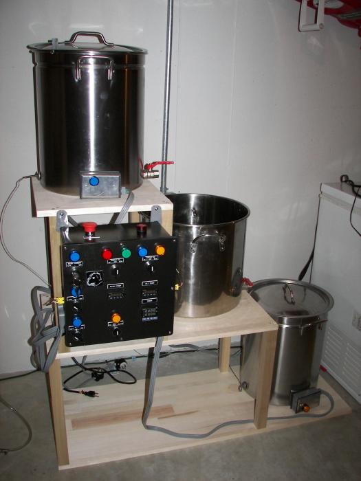
Pretty much followed the above diagram, and it came out like this. I have a few plumbing items to finish up, and a few wiring changes and it will be functional.

0408931407004.jpg
 
Back
Top