Etching a circuit board from scratch

Homebrew Talk - Beer, Wine, Mead, & Cider Brewing Discussion Forum

Help Support Homebrew Talk - Beer, Wine, Mead, & Cider Brewing Discussion Forum:

This site may earn a commission from merchant affiliate links, including eBay, Amazon, and others.

chuckjaxfl

Well-Known Member
Joined
Feb 16, 2010
Messages
331
Reaction score
23
Location
Jacksonville, FL
Despite there being a $7 solution commercially available, I'm going the slower, more painful, and more expensive route. I'm going to try to build my own PWM from plans I found on the net.

Here's my first attempt at etching. Not a success, but encouraging for a first attempt!

6852522100_09e4f57507_z.jpg


I'll take pics of the process on the way through next time.
 
Looks great! I haven't done that since a long, long time ago.

Yoiu might be able to get some conformal coating at radio shack. Mask the places you want to solder with tape and spray away to keep the conductive traces from corroding.

Otherwise maybe some spray polyurethane from home depot.
 
Just out of interest, why are there holes in the vias? Assuming you're going to drill those anyway, you should just make them solid...

Cheers!
 
Just out of interest, why are there holes in the vias?

I've always found holes in the vias act like a pilot hole when drilling - the bit catches nicely if you've sized the hole properly.

Chuckjaxfl - I assume you're doing toner transfer. Lot's of folks on the interwebs suggest using photo paper, but I've found that makes really poor transfers. If you haven't already tried it - use glossy magazine paper. Just rip a page out of one of those magazines lying around the house and send it through your laser printer. If your printer jams on thin paper, try folding it over a normal sheet of printer paper.
 
The holes are there because that is the default in the software. When I figure out how to change it, I will make the holes smaller, at least if not remove them completely.

Yes, I'm using laser toner, and pages from a Northern Brewer catalog.
 
chuckjaxfl said:
The holes are there because that is the default in the software. When I figure out how to change it, I will make the holes smaller, at least if not remove them completely.

Yes, I'm using laser toner, and pages from a Northern Brewer catalog.

Oh, and I'll make all of those traces the 'fat' size. That seemed to work better than those thin lines.
 
The holes are there because that is the default in the software.

What software are you using? I've been using ExpressPCB for years - very easy to use and free. Their schematic software is great too - I designed the electrical system for my kitplane using it.

Oh, and I'll make all of those traces the 'fat' size. That seemed to work better than those thin lines.

You should be able to go much thinner without issue. I commonly run 0.010"/0.015" traces with this process. In fact, I've found that wider traces need better technique than thinner ones. From your photo, it looks like you might have had uneven heat/pressure application. Getting the ironing right really is the most challenging part.

This has reminded me that I have a tub of spent ferric chloride I need to bring to my town's hazardous material drop off day...
 
I've made pcbs before. What I'd do is order some copper clad board, order some uv film.. Then I'd take the uv film and laminate to the copper board. I'd make my circuit with a pcb program, print that on projector film with a laser printer. Id take that image and lay it on the board. Then I'd place it in a uv light enclosure I built and exposed it for a few mins. Then I'd take a film remover and removed the film that was exposed but the circuit traces. Then id drill my through holes. After that I etched the pcb board with some peroxide and muriatic acid.
 
Couldn't resist (<= no pun intended) posting a screen shot of a pcb I designed earlier this Fall. It's a tight close up looking through a pair of nand flash chips (double-sided BGAs) with six of ten layers showing. This is on a 1 Terabyte solid state disk board, which in its entirety measures a mere 1 inch by four inches. This one is being sold for the MacBook Air and its performance and capacity totally kicks the stock Apple SSD to the curb.

Feature size is pretty much standard for this type of work: 0.1mm wire with 0.1mm gaps, vias use 0.45mm diameter pads with a 0.2mm drill. Using Cadence Concept for schematics and Allegro 16.5 for layout...

six_of_ten.jpg


Cheers!
 
Oh gee, thanks!! I was all proud of my work, thinking I was pretty cool there for one day. Then you guys have to come in and show me up, making my PWM board look like a scout project and all!

In all seriousness, that looks like interesting work! Tedious, and mind consuming, probably like writing code. (I.E., I'll just finish one more part, then I'm off to bed.... 4, 5, 6 hours later.)

I now know who my "go to" guys are now if I run into a snag later!
 
I think I accidentally ran off passedpawn! I'm just joking, put your oxygen sensor back up there! That was cool looking!

I ordered a sackful of components from Hong Kong - sheesh this stuff is WAAAY cheaper than brewing or reloading!

20 555 timers
20 8 pin sockets
2 1M Pots
50 1k resistors
50 470 resistors
50 1n4001 diodes
50 0.01uf caps
20 4.7uf caps
added some leds & bezels.

All for about $15 - free shipping.
 
Oh gee, thanks!! I was all proud of my work, thinking I was pretty cool there for one day. Then you guys have to come in and show me up, making my PWM board look like a scout project and all!

In all seriousness, that looks like interesting work! Tedious, and mind consuming, probably like writing code. (I.E., I'll just finish one more part, then I'm off to bed.... 4, 5, 6 hours later.)

I now know who my "go to" guys are now if I run into a snag later!

LOL! Yeah, that last part is an occupational hazard. I'm just finishing up work myself.

Temporal thread drift...

When you're working with 10 layers and a hundreds of nets that have to be length-matched to within five thousandths of an inch, you have to be able to get into a certain zone or you're totally dead meat on a stick. Some folks definitely find that tedious, mostly 'cuz they just can't get into that zone. But when you're in there, it's a whole 'nuther world ;) Time almost stands still and all kinds of good stuff just happens. I imagine good coders find the same paradigm exists for them.

fwiw, I was actually retired after almost 40 years in computer hardware design. I worked for a lot of players, IBM, Digital, Compaq, HP, Stratus, and did some midnight designs for other outfits like Honeywell and EMC at the same time. Never wrote a resume, people just came knocking. Someone who worked for me ten years ago talked me into consulting work, and I've designed 10 boards since late August. The first two were introduced at the CES in January and were well received.

The best part of it all is my commute is like 20 seconds, I don't have a manager or a board of directors doing utterly stupid stuff, and I get paid for doing what I've always enjoyed doing. Plus I can hit my keezer any time of the day if I need to take the edge off a tad :mug:

It's definitely a pretty cool gig. Highly recommended...

Cheers!

[we now return you back to your thread, which is already in progress ;) ]
 
if using the glossy magazine paper method remember that etch resistant pen is your friend, I have etched a lot of boards recently using this method and sometimes i needed to use the pen to fix up a trace before etching. There is nothing like making you own stuff, I almost always go down the DIY route and most of the time it ends up cheaper.

cheers steve
 
I played with this for a bit. Trying different things with magazine paper and acid/peroxide solution. I have found the first etch is awesomely fast, then the next time I try, a few days later, the solution takes practically HOURS.

I did get a nice working PWM circuit etched and plan to do a few more.

I might have to find an etch resist pen. I have found that the transfer of the toner is not always perfect, and that might help keep the traces whole.

It's fun stuff.
 
Also, I just took a screen shot of the original board and did some basic photo editing to get a black and white trace pattern. No board software needed, even though I also downloaded the Eagle software to play with for custom boards if I ever need to build one from scratch.
 
I still got the equipment haven't been using it (laminator, uv light box, the uv film, etc). Reason why I didn't use a pcb manufacturer cause they are expensive for small runs.
 
I got my parts in from eBay.

The circuit works as designed on a breadboard, at least. If it doesn't work on the pcb, at least I'll know it's not a circuit design flaw.

It's been running for about a day and a half on this set of batteries, which I scavenged from a camera flash.

image-1328489536.jpg

The pulse width changes smoothly across the range, which surprised me. I hooked my ohm meter and the rating seemed to adjust in clumsy 'jumps' instead of a nice smooth curve when turning the knob on the pot.
 
X2 on the sharpie. for thick traces I just go over the toner with a sharpie and it really helps. toner is porous and lets the etchent through, damn I forget how to seal it...
 
For you guys suggesting Sharpies, do you mean to use it for the UV exposure, photo resist? I'm just transferring toner off of a page from a Northern Brewer catalog, then etching. Does the Sharpie resist the actual ferric chloride (? I forget the name, I'm not at home) etch solution?
 
No the sharpie provides a protective layer on the trace so that the etchant won't eat the trace.
 
Czm said:
No the sharpie provides a protective layer on the trace so that the etchant won't eat the trace.

Yes I meant.
 
If the trace (once transfered from paper to copper) is not perfect, you can touch up the trace on the copper. It will protect the copper the same as the toner does, when the etchant eats away the exposed areas.

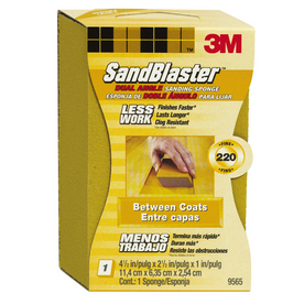
once done, it will scuff off same as the toner with a scotch-brite or a very fine sandpaper block. this thing works great! Then, a drop of solder where your pads are and cover with paint or epoxy to minimize the oxidation.

051131999510lg.jpg
 
Back
Top