Definitely fired my SSR now more curious as to the why and the how

Homebrew Talk - Beer, Wine, Mead, & Cider Brewing Discussion Forum

Help Support Homebrew Talk - Beer, Wine, Mead, & Cider Brewing Discussion Forum:

This site may earn a commission from merchant affiliate links, including eBay, Amazon, and others.

flananuts

Supporting Member
HBT Supporter
Joined
Dec 2, 2008
Messages
506
Reaction score
1
Location
Monmouth County, NJ
Last brew session, my bk electric element failed right while I was sparging to the BK. Fortunately my HLT is closely identical to my BK and I was able to still finish my brew session.

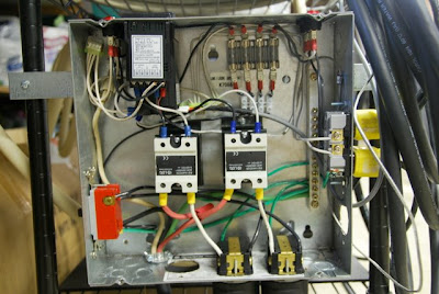
I tested the voltage on my SSR and found that I was getting a full 119v on the connection to my element even when the PID was off. So I'm aware that it's not supposed to be this, but shouldn't the element still run at full 4500w 240? Or is the voltage slipping through but there amps are there to produce the proper wattage?

I'm ordering a new SSR but would love to get anyone's opinion or experience with SSR failure.
 
When you say "tested the voltage", from where to where did you test? The SSR output lug to ground?

I'm assuming the system is 240v. Is the other leg of the element hot all the time? If so, then you'd always read 120v from the output of the SSR to ground because of the voltage going through the element from the other leg.

What voltage do you read across the two lugs on the element?

-Joe
 
Here's the voltage when testing across L1 and T1. On the SSR that will fire the element up, the voltage is minimal, maybe 0-3 v fluctuating at most. On the SSr that won't fire the elements, I measured 240v when testing across L1 and T1
 
I think we'd need a wiring diagram to say for sure. Testing across L1/T1 won't tell you much, since that's just the power side of the relay. I still wouldn't expect to see 240v there, which is why I'd like to see a wiring diagram of your system.

You should be able to check if the SSR is working at all by disconnecting L1 and T1 from power entirely and checking the resistance between L1 and T1. It should be infinite if the SSR is off, and a very low resistance if the SSR is switched on.

-Joe
 
You will always measure voltage across the load leads of an SSR. SSRs switch current, not voltage. Even in an off state, SSRs leak a few mA. Enough for a sensitive instrument like a multimeter to read the voltage.

Use a proper load to test an SSR, like a table lamp, for instance.
 
So I load tested using the 4500 240v camco ripp element. SSR that read 240v across L1 and T1 would not fire up the element. SSR that fired up the element read very little voltage across L1 and T1. I'll test resistance when I get home tonight however I'm pretty sure that it's toast.
 
Again, you cannot measure voltage across L1 and T1 as a meaningful test. SSRs do not switch voltage. If the SSR did not fire a known working element while an input signal was being applied then it sounds like it's dead. That is unusual as SSRs generally fail closed (the element would always fire regardless of input signal).
 
Yeah, I got that with your last post, and I'll definitely test resistance tonight. I would say that based on your note about the SSR failing(edit) open makes sense if I'm seeing 240v between the two poles on the failed SSR. One hot runs through the lead to the element and back to the SSR measuring 119v load to ground. Other side of the SSR measures 119v load to ground. So in theory testing the two poles on the SSR would be just like testing the two hot leads directly from the breaker.

In regards to measuring resistance, my multimeter has a number of settings, which one should I use?
 
Sorry flananuts but you're not getting it. In a working OR failed SSR, you should ALWAYS read voltage. SSRs do nothing to voltage whatsoever.

The reason you saw "very little" voltage across the working element / SSR was you set up a circuit called a voltage divider. Your element has just a few ohms of resistance whereas your meter has nearly infinite resistance. The electricity prefers the path of least resistance, giving you the "very little" reading on your meter.

The fact is, you very likely don't have the necessary equipment to electronically test an SSR. Most hand-held multi-meters can only handle an amp of current at most - not 40-50. Testing resistance is also completely meaningless. SSRs need a minimum load for switching to occur.

Fortunately, you don't need a meter to properly test an SSR. Just use a lightbulb. In your case, you'll need to find a 240V bulb unless you've got access to the neutral wire. Your SSR is only switching one leg of 240V which is also 120V to neutral. So, if you instead wire one lead of a 120V light socket to neutral and the other to your SSR, you should have a nice, instantaneous visual indication of whether your SSR is responding correctly to input signals.
 
I do get your point on the lightbulb test and I do have access to a neutral, so I will attempt this test. I plan to also connect my other PID to this SSR and see if I have a PID issue.

Thanks for being patient with me. I've brewed a dozen 10gal batches on my rig and now my rig is "lame" so I need her fixed.

Here's a pic of the control box in case you want to see . The SSR on the left is the one not playing nicely
DSC_0300.JPG
 
Okay, update. I hooked up a lightbulb to the SSR and set my processor to PID status. The initial test of DV voltage was within the range of the SSR. So I hooked up the lightbulb and turned on the voltage and the bulb pulsed inline with the led in the ssr. So I changed the processor to manual on. The LED lit up on the SSR however the bulb did not stay on. I turned it back to PID and the ssr was pulsing but the bulb wasn't.

Now what should I test?
 
kill power to your panel> i.e. unplug it or turnn off breaker ...depending on what your using.. read ohms accros the element... if you see infinate resistance(ohms) or extremely high, you burnt up your element> Like when you burn up a electric hot water heater in you home..... if you do see some sort of lower resistance turn on power to you panel in a condition so the element should be in the off postion. read voltage across the output of you SSR ( in your config you should see 240V) now make adjust your system so your element should be in the on position continue to monitor voltage, when the realy picks up the "potential difference" across the point should be 0 and you will read 0Vac indicating that the realy did infact switch states.
 
Okay, update. I hooked up a lightbulb to the SSR and set my processor to PID status. The initial test of DV voltage was within the range of the SSR. So I hooked up the lightbulb and turned on the voltage and the bulb pulsed inline with the led in the ssr. So I changed the processor to manual on. The LED lit up on the SSR however the bulb did not stay on. I turned it back to PID and the ssr was pulsing but the bulb wasn't.

Now what should I test?

If the SSR LED is on, but the load (lightbulb in this case) is off, then the SSR is toast. Did you try testing the other SSR as well?
 
read voltage across the output of you SSR ( in your config you should see 240V) now make adjust your system so your element should be in the on position continue to monitor voltage, when the realy picks up the "potential difference" across the point should be 0 and you will read 0Vac indicating that the realy did infact switch states.

Huh???

You might want to go back and read the full thread to get up to speed.
 
Ohio-Ed, I may be from NJ, but I deserver a little more credit than that :) The bulb survived and is back in it's socket working nicely lighting up a dark part of my basement.

jkarp - based on your suggestion on testing current with the lightbulb, and also naedum5's comments(even thought you don't agree with the method for testing), my SSR is indeed toasted with a light smear of thermal grease butter!

Thanks for all the help.
 
flananuts - SSRs are stupidly rugged devices. I used to work on entertainment lighting systems and saw maybe two or three out of thousands fail. Make sure you've got sufficient heat dissipation as that's about the only way to kill 'em.
 
Thanks man. I have pretty decent sized heat sinks that are mounted to an all metal box. I've never noticed them to be more than a bit warm. I was using a SPDT 20amp switch to manage one leg of power. That failed at the same time my SSR and element went kaput. I now have a 40amp contactor managing the juice so hopefully I won't have an issue. Maybe I had the 1/1000 one to fail.

On another note, what type of lighting systems do you work on? I paid my way through school working as a local stagehand in the DC area. My favorite job was either climbing in the lighting trusses during a load in, or working the board at FOH through the lighting routines.
 
I just found this, which is interesting in relation to your failure:

One disadvantage of solid state relays is their tendency to fail "shorted" on their outputs, while electromechanical relay contacts tend to fail "open." In either case, it is possible for a relay to fail in the other mode, but these are the most common failures. Because a "fail-open" state is generally considered safer than a "fail-closed" state, electromechanical relays are still favored over their solid-state counterparts in many applications.

That is good to know.

-Joe
 
Back
Top