Help, I bought and electric brewery and want to rewire it.

Homebrew Talk - Beer, Wine, Mead, & Cider Brewing Discussion Forum

Help Support Homebrew Talk - Beer, Wine, Mead, & Cider Brewing Discussion Forum:

This site may earn a commission from merchant affiliate links, including eBay, Amazon, and others.

67cougargt

Well-Known Member
Joined
Aug 21, 2011
Messages
64
Reaction score
1
Location
Topeka
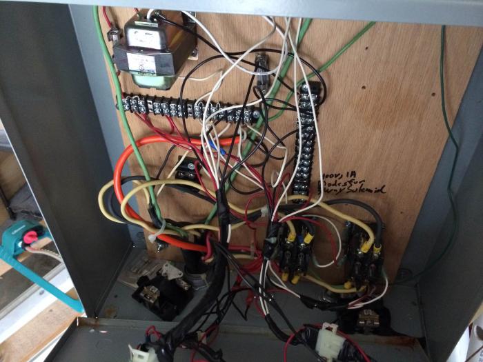
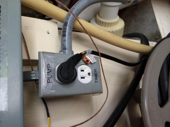
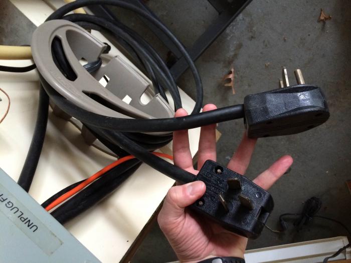
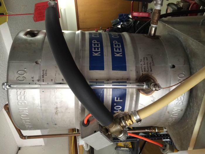
I am looking for help taking an electric brewery I purchased from someone else and rewiring it to be safe and to make the best use of the parts already in use. Because it already has two elements in the hot liquor tank, (4500 and 5500 watts) I would like to utilize them for the quick heating time. The previous owner used gas for boiling independent of this panel. I would like to go all electric and convert one of my keggles to electric for boiling. I think this diagram by PJ, less the extra element in the boil kettle is what I would like to do. I have purchased a 60 Amp GFCI breaker switch and 6-3 wire with ground to run to the control panel. I would like the ability to run all three elements at once to do back to back brewing. Looking at the panel switches and PID’s(CAL 9900’s) I already have, I think I need to add din mounted breakers and SSR’s and wire an emergency stop. I would appreciate any input into best utilizing the components I have and making the system safe. Thanks!
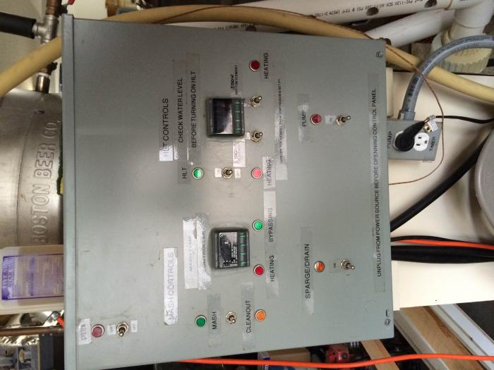
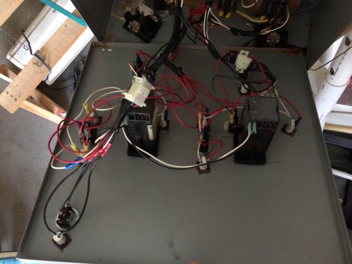
photo1.jpg


photo4.jpg


photo5.jpg


photo8.jpg


photo7.jpg


photo2.jpg


Auberin-wiring1-a11b-RM-SYL-2352-5500w.jpg
 
I don't know if it makes a difference or not in receiving responses or help. I have been freeloading on here long enough. I have become a supporting member.
 
Here is the normal post of the image you referenced.

As always click on the image to see and save a full scale diagram printable on Tabloid paper (11" X 17")


Switch 6 selects either the HLT or the BOIL elements. With the power delivered (60Amps) you will not be abe to run 3 elements at one time unless all of them are 4500W or less and a max of 3 elements are used. Even with 3 4500W elements you are running really close to maxing it out. (56.25 Amps)

I hope this helps you.

P-J
 
Yes it does, I very much value your advice. I have read many of your posts and respect the concerns for safety. Enough that I could tell this would not be good to use as it is currently configured. There is no ground to the elements, no SSR's just relays, and I knew I would need the GFCI protection. With my GFCI in the breaker box will the 120v pump running during recirculation and the 240v heating element running create a power imbalance and trip the GFCI?


Thank You!

Jim
 
Yes it does, I very much value your advice. I have read many of your posts and respect the concerns for safety. Enough that I could tell this would not be good to use as it is currently configured. There is no ground to the elements, no SSR's just relays, and I knew I would need the GFCI protection. With my GFCI in the breaker box will the 120v pump running during recirculation and the 240v heating element running create a power imbalance and trip the GFCI?
Jim,

A few things. You say - "no ground to the elements" - Check the diagram. The elements are grounded - follow the green lines going to the element outlets.

You say - "no SSR's just relays" - The diagram shows 4 SSRs. It is a different image on this diagram as there are several in place and I tried to conserve drawing space.

You are concerned about - "GFCI protection" - You can place a GFCI breaker in your mains panel or set up a GFCI Spa Panel. Take a look at this posting: gfci-protection It gives the source for the Spa Panel and the wiring of it for the system.

Running 240V and 120V devices at the same time also provides balanced power and will not affect the GFCI breaker.

I hope this helps you.

P-J
 
I think Jim is talking about the panel he bought, not about your drawing, P-J. :)


Sent from my iPhone using Home Brew
 
P-J, sorry I wasn't clear I know your diagram is right.
Here I was talking about what I purchased, "Enough that I could tell this would not be good to use as it is currently configured. There is no ground to the elements, no SSR's just relays, and I knew I would need the GFCI protection."

I am trying to determine what I have? and what do I need to do it to bring up to your standard?

Thanks,

Jim
Sorry.

Wishing you the best.

P-J
 
Hey cougar,

I don't think being a paid or free member is a factor in getting input. I would suggest reading up about electric brewing a bit more and then ask very specific questions. To me, it seems like you are in over your head right now, but with some research you can get it working.

As is, your post for help is pretty vague. I would also recommend taking a little bit of time to turn your pics so we can see them better?

Take care,


I don't know if it makes a difference or not in receiving responses or help. I have been freeloading on here long enough. I have become a supporting member.
 
I guess I was trying to save space by asking all my questions up front in one post rather than in multiple posts. Forgive me as I have read much on here but was not completely sure about how to ask for help. I don't know why the pictures posted sideways. I thought someone with greater knowledge and experience than I, might look at the panel and guide me to a diagram that is similar in purpose and design to what I have. Then I could purchase the needed components to follow a proven safe diagram. Thank you, I do appreciate your input.
 
This is one of those things that really should be taken care of in person instead of over the internet. You might want to join a local homebrew club and see if any of the members are electric brewers that have set up their own rig. But I'll see if I can help.

If this were my setup, I'd just rip out all of those wires inside the control panel and start over. It's a spaghetti mess and I think it would be a nightmare to try to track down wiring problems. But if you don't know much of anything about wiring these things up, that means you're going to have some considerable down-time while you learn about this stuff.

I'd also get rid of that plywood board inside the control panel and replace it with a piece of thick sheet metal. I don't like the idea of some electrical component frying and then the rest of my panel catching fire. But that's just me.

As for the non-grounded elements...how do you know they're not grounded? If they are 240v elements, they should have two wires supplying power and one wire for ground. Heating elements don't have (or need) neutral wires.
 
I agree with everything you said. Especially that is easier and better to communicate in person than it is using messages. I am a member of great brew club "The Greater Topeka Hall of Foamers". I have a friend in the club who is helping me with this project. When I bought the system and looked at the wiring I decided I would by if for parts and get a diagram I could follow and start over. The plywood bothers me as well as far as the elements, I took a picture with the covers off the elements one four wire cable is used to power both elements the ground and neutral wire are both carrying voltage. I appreciate you responding and looking at the photos for me it helps to confirm what I have been thinking all along.

DSCN2970.jpg
 
Yeah...that doesn't look grounded. That green ground wire might be a smaller gauge than the other ones as well, so powering the rig with it would be even worse. Some people just do not care about their safety at all.
 
Also of note - it looks like the original builder used plastic junction boxes, so you wouldn't expect to see a ground wire inside those boxes because the element doesn't have a ground lug - it's grounded via its contact to the kettle. Of course, you need to verify that there's actual contact between the kettle and the element to get a good ground (use a multi-meter on Ohm setting). Then install a ground wire with a sheet metal screw into the bottom lip of the kettle (the part that isn't holding liquid, the rim as it were) so you can ground the kettle and the element.

I agree with the others - rip a lot of it out and start fresh. Trying to reverse engineer someone's decisions and layout, without knowing how or why they did what they did... I hate to say it, but I think you're going to spend a LOT of time and headache paying for whatever you saw in savings buying this thing.

-Kevin
 
That's definitely not grounded. Not grounding is a safety concern.

They definitely used a 4-wire cable to power to the two heating elements. As BadNewsBrewery mentioned, the green may be undersized as well, making it undersized for the current that is passing through. This would be a serious issue every time it is used. At the very least check all the wires to make sure they're sized correctly for the amperage they are meant to carry.

Kal
 
Back
Top