Lucky_Chicken
Well-Known Member
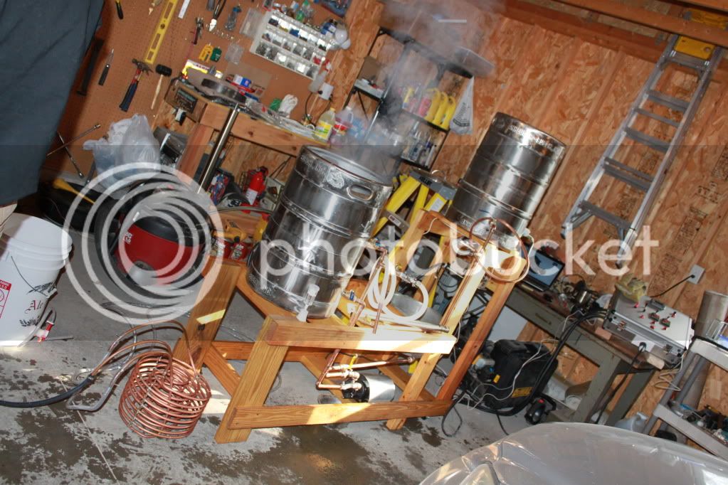
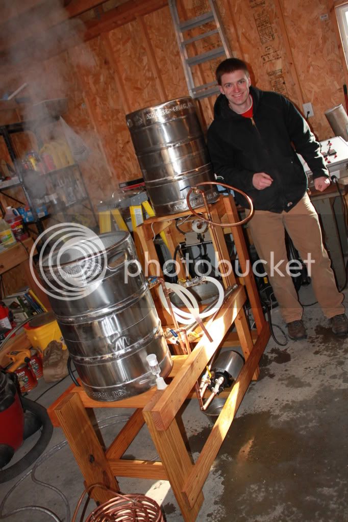
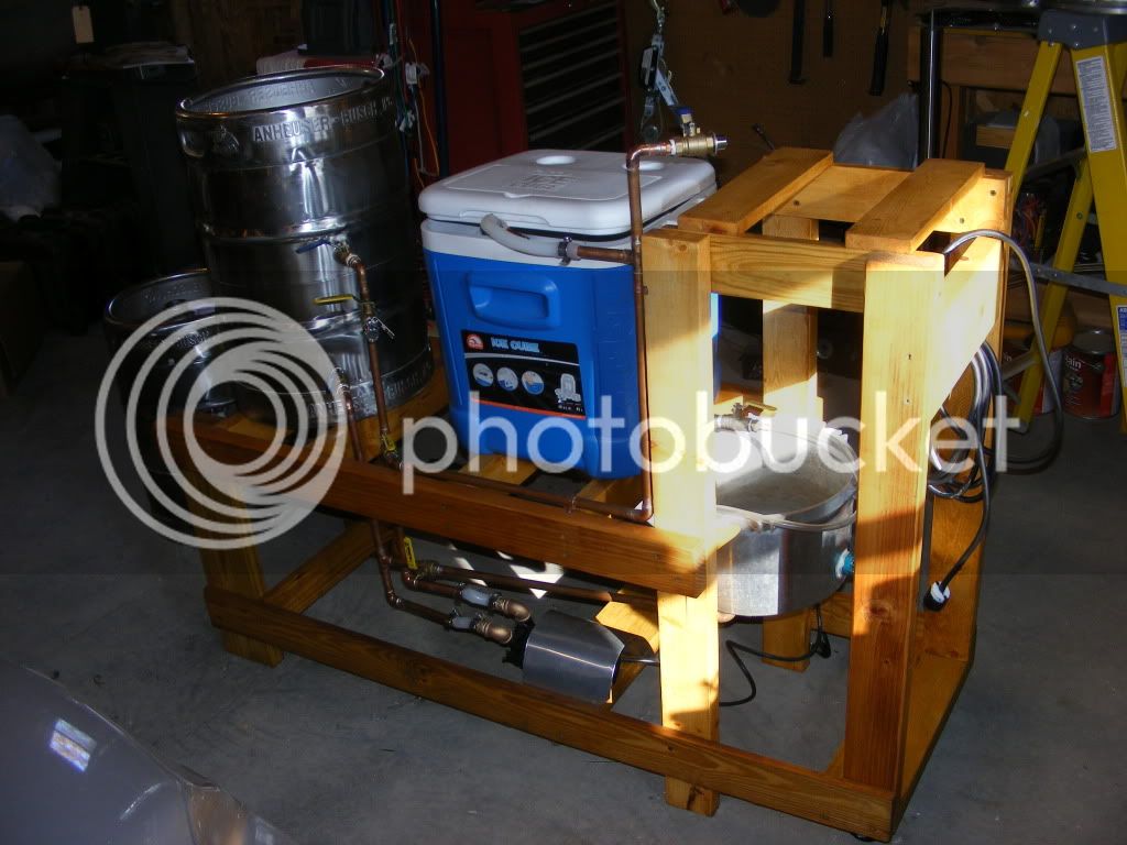
So... we got a bonus this year, so the wife said I should do something for me. That means building an all electric rig so I can brew indoors in bad weather. I will keep this updated with my progress.
What I am thinking so far:
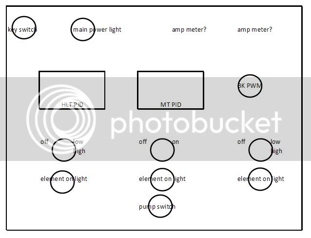
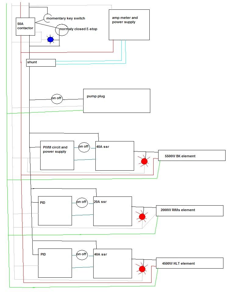
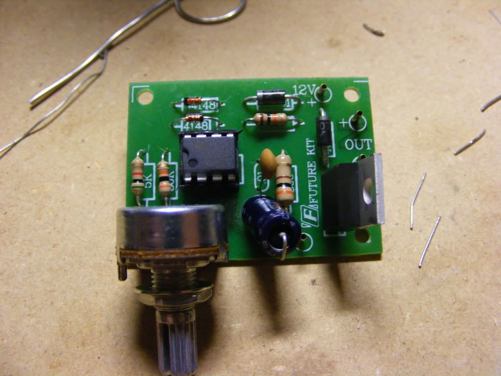
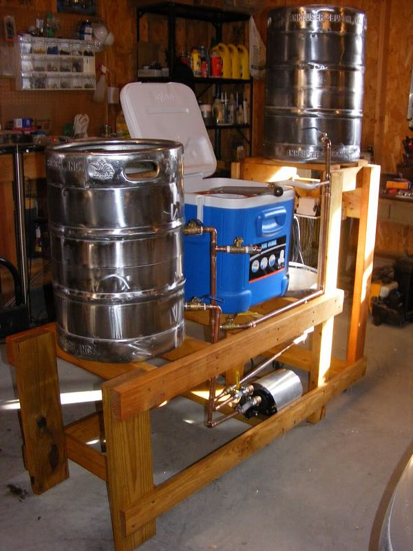
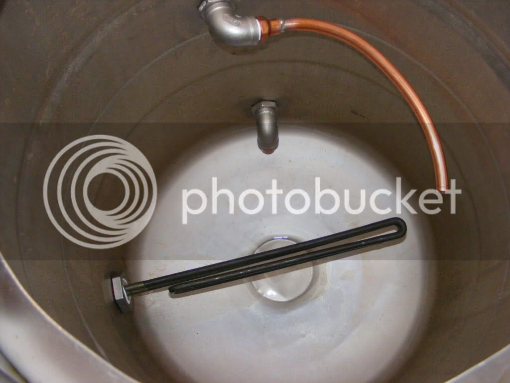
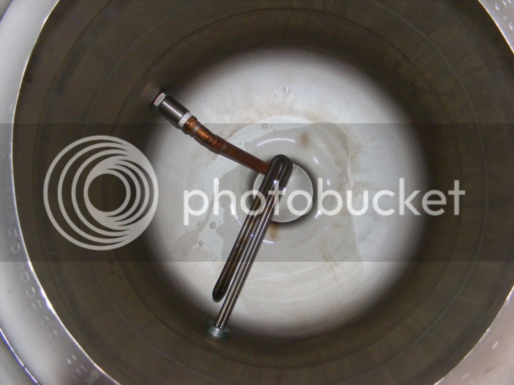
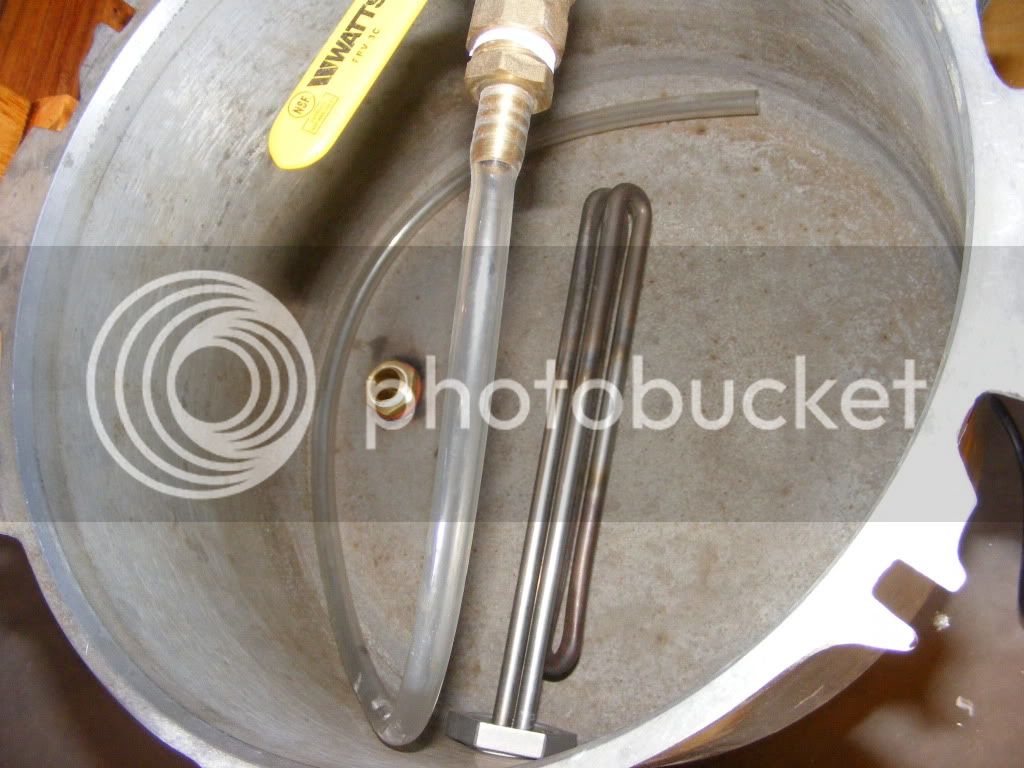
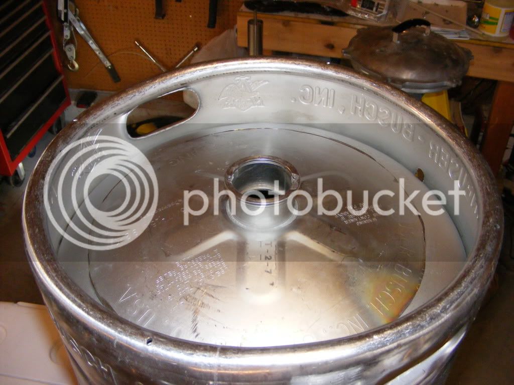
5500W keggle for the boil run on a PWM circuit
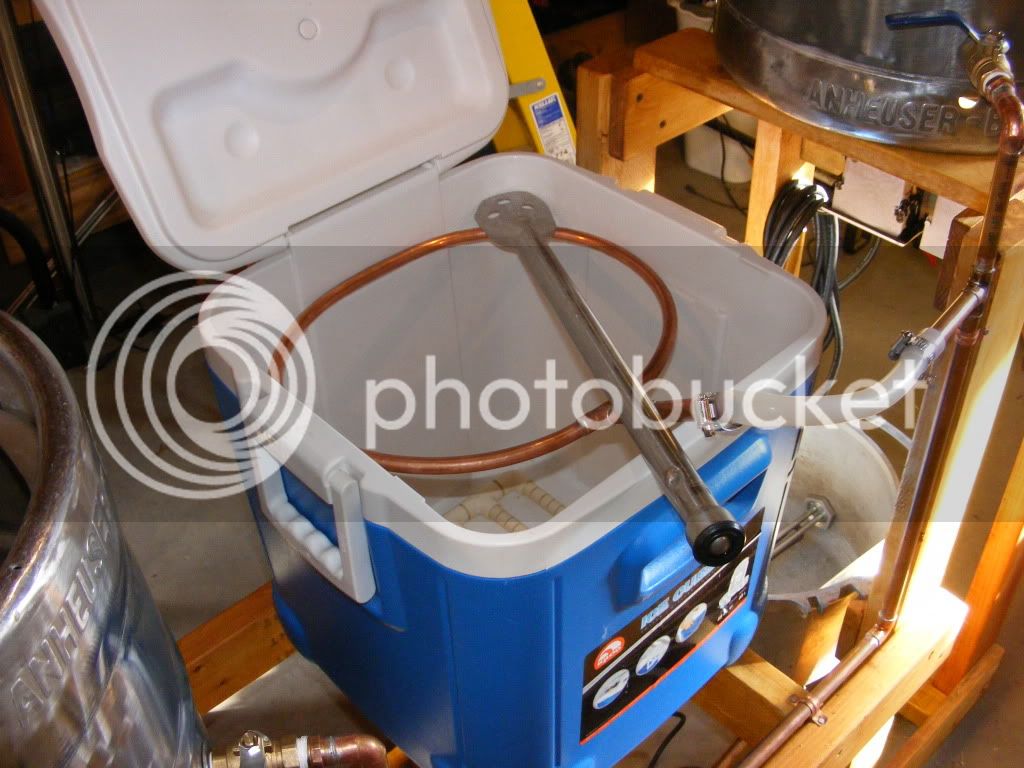
2000W? RIMs tube run on a PID from my current plastic cooler MT
5500W keggle for the MLT on a PID circuit
I may try to control the output to the two 5500W elements so I can run them both at partial power?
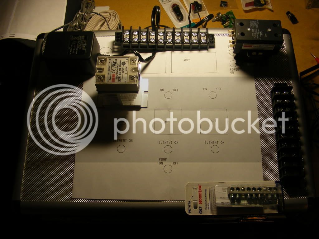
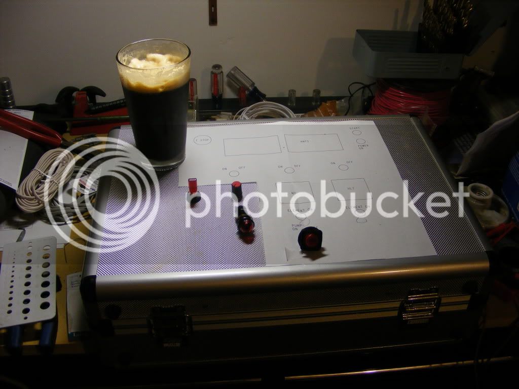
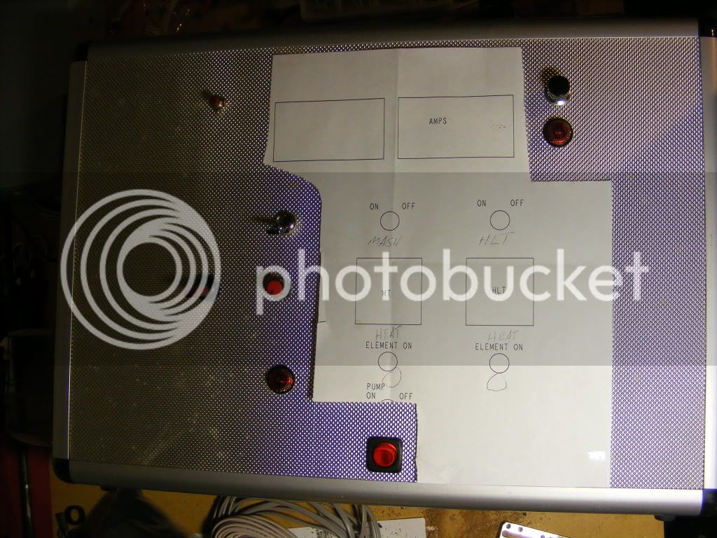
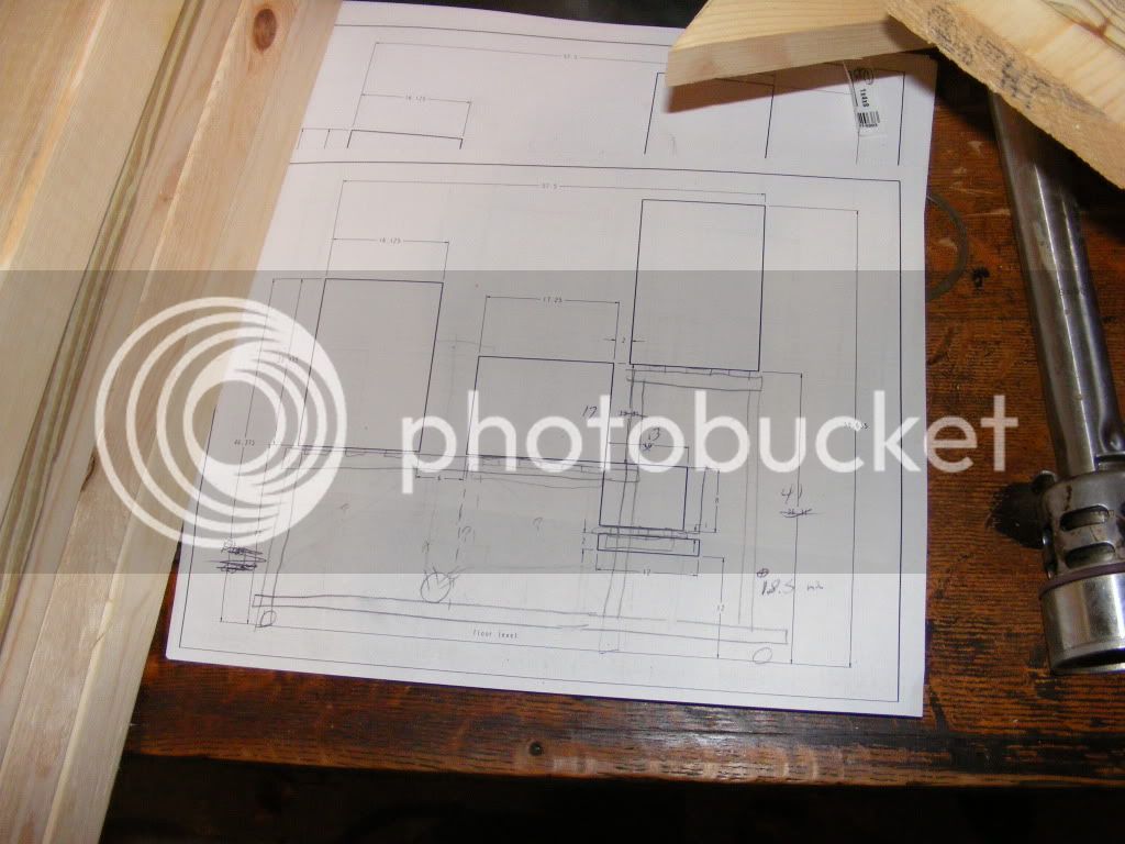
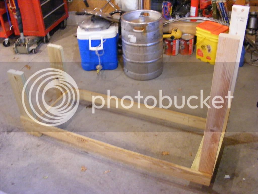
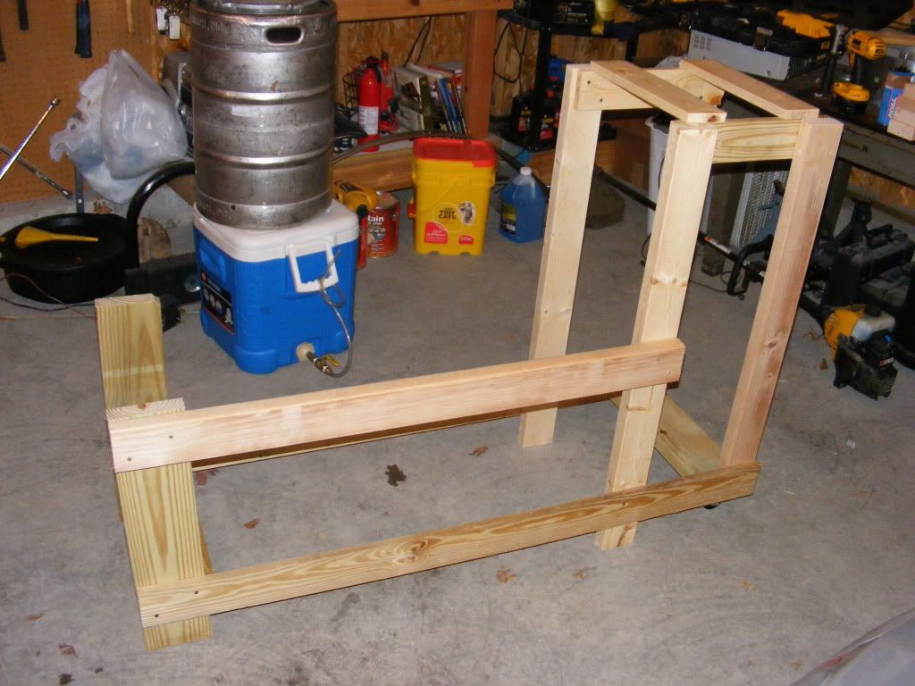
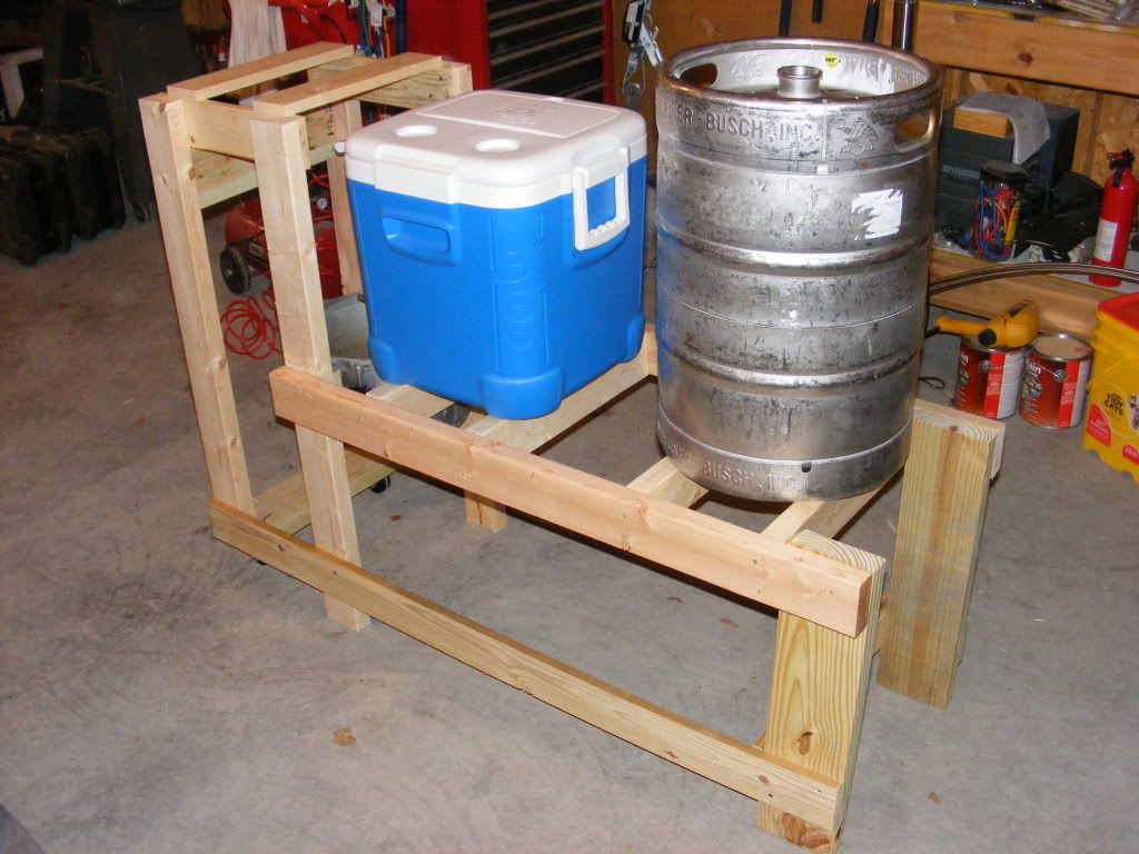
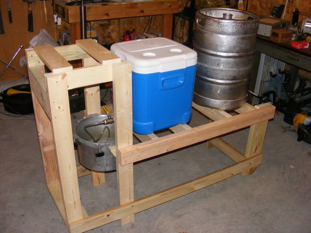
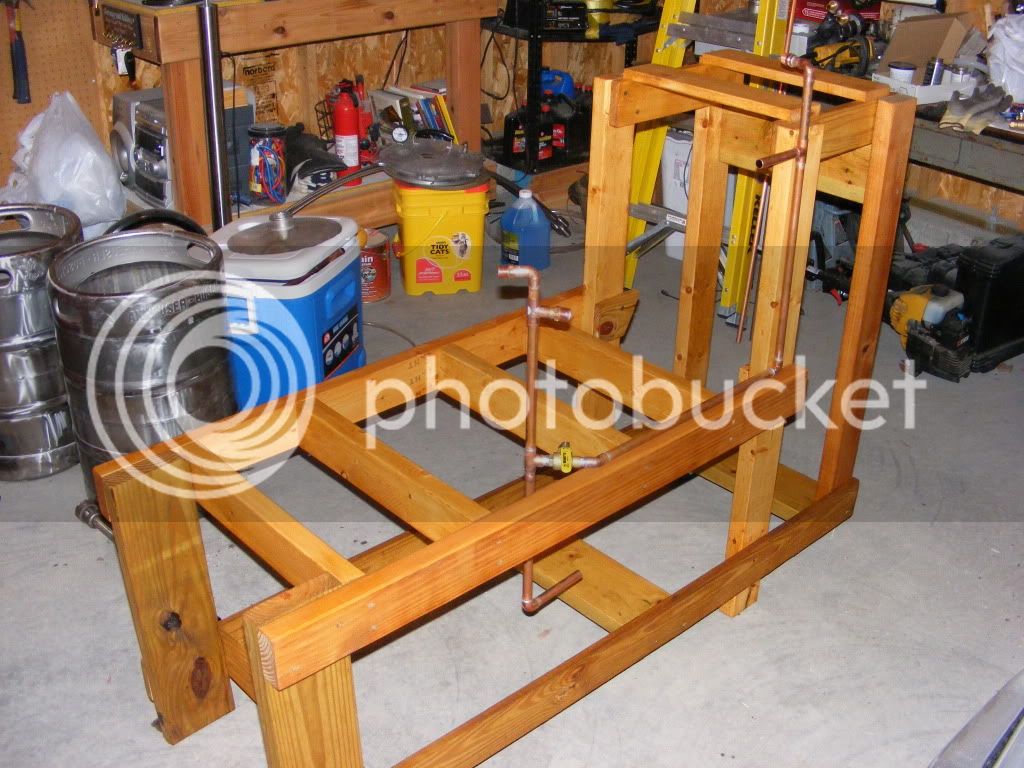
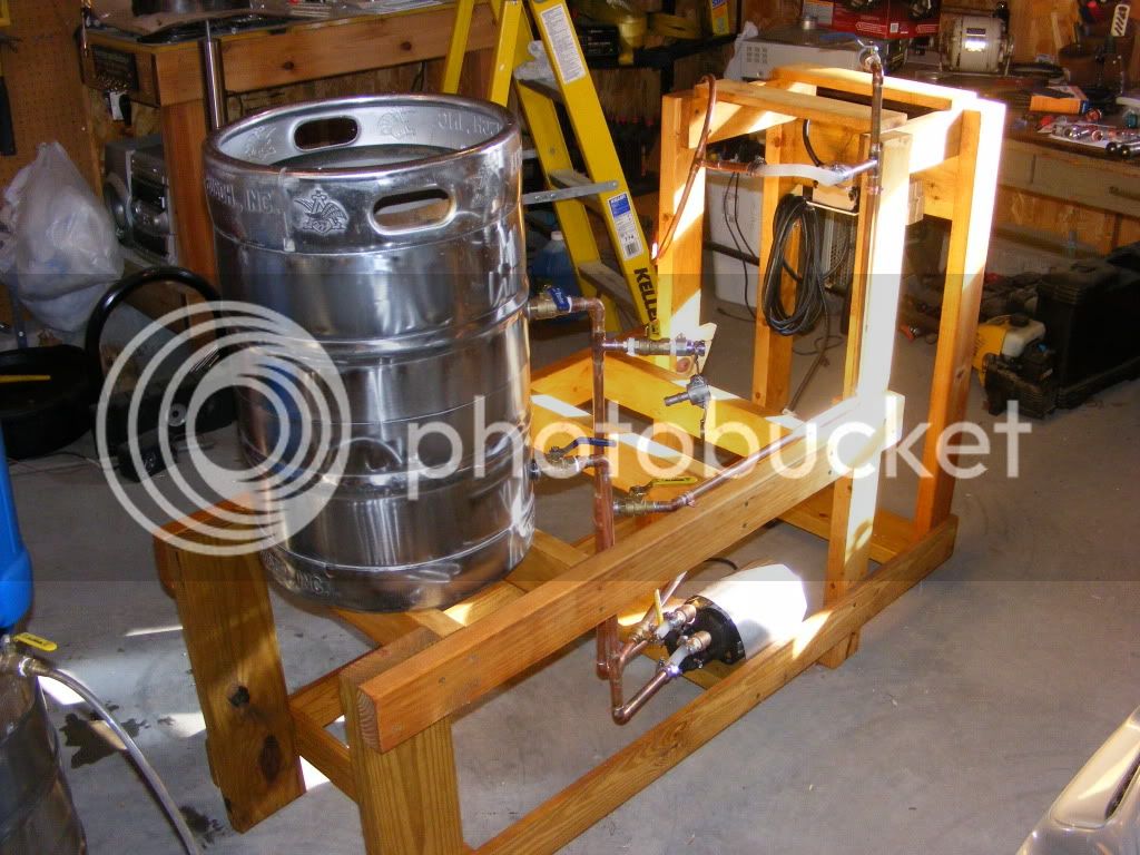
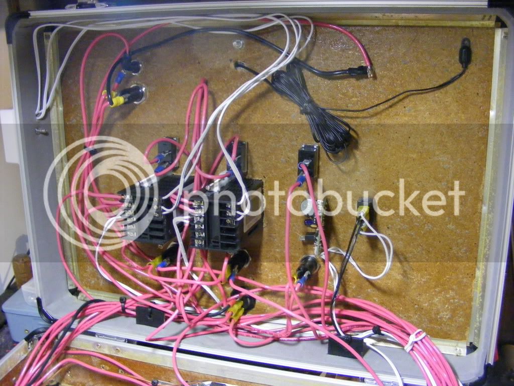
I will be building the stand out of wood and sealed with some deck stain. I thought about using an old computer case for the control panel (but it wont be water proof) not sure if I will, but that would allow low voltage controls for cheep since it already has a power supply.
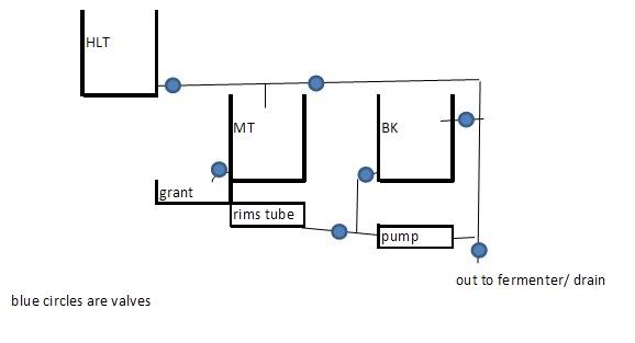
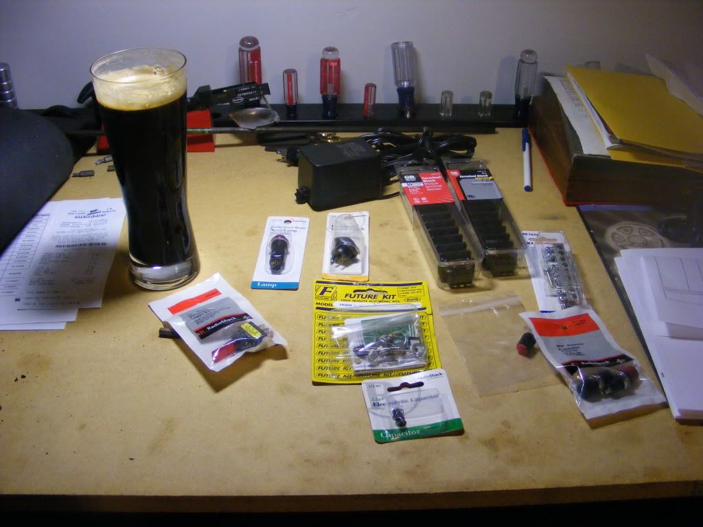
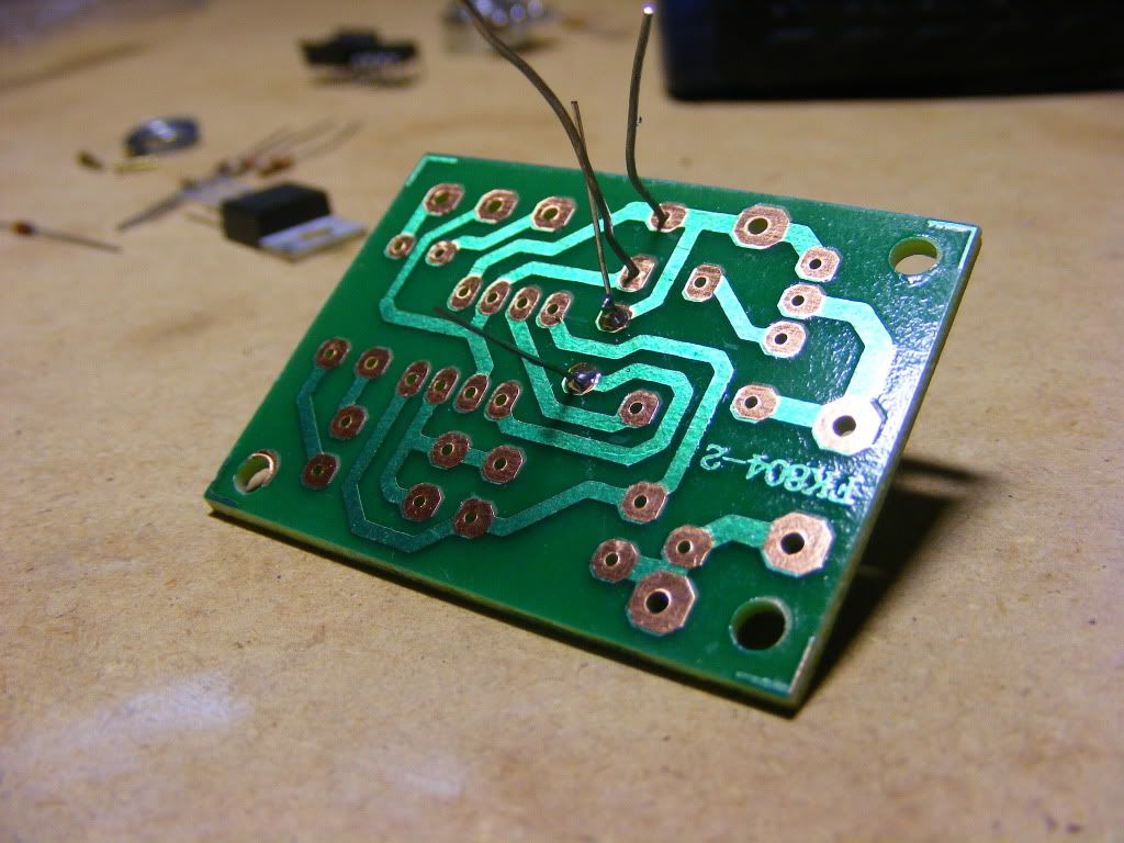
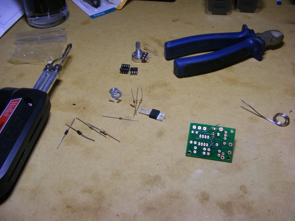
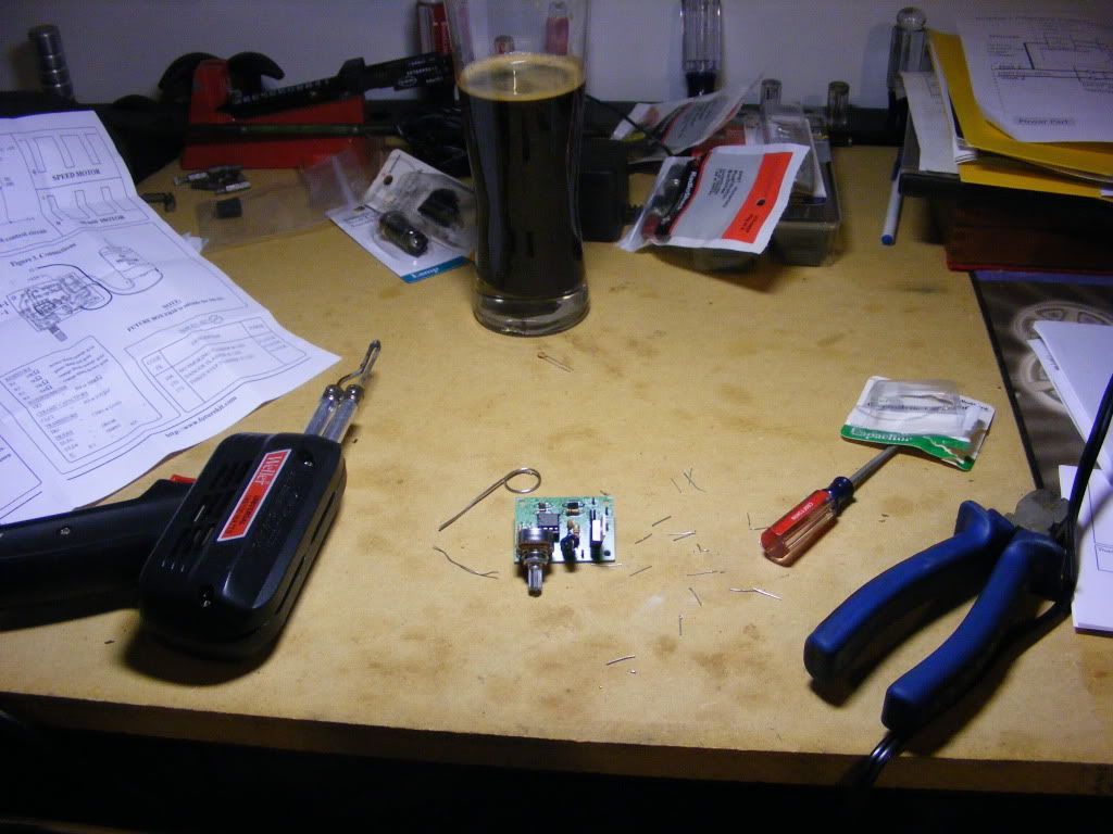
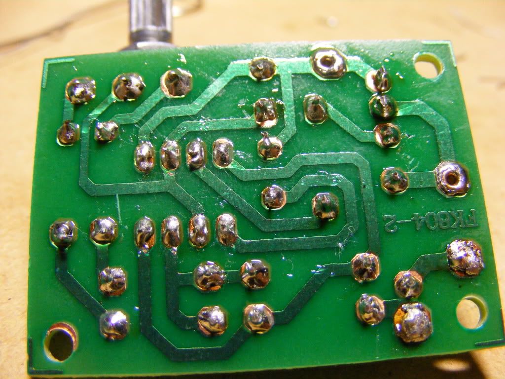
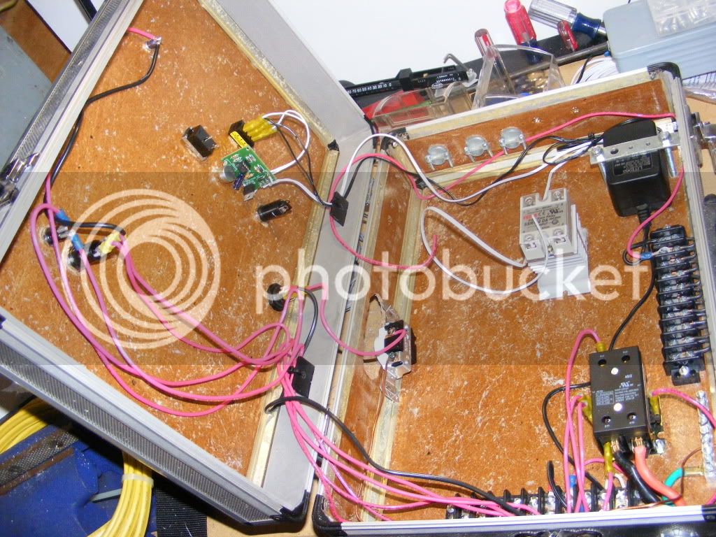
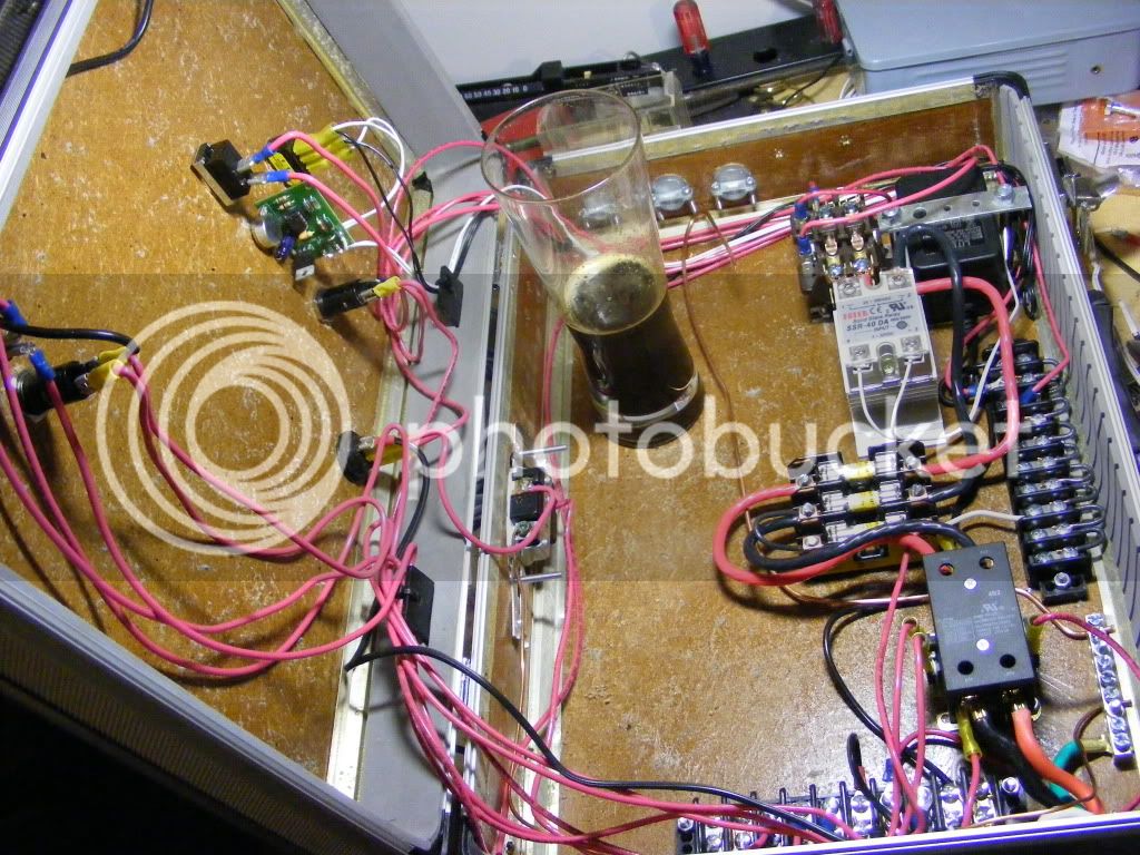
So far the only things I have on order is the stuff to set up the PWM circuit. I am working on a wiring diagram and a brew stand layout, I will post them when I like them.
Let me know your thoughts or what you would do differently on yours. Thanks ahead of time!
What I am thinking so far:
5500W keggle for the boil run on a PWM circuit
2000W? RIMs tube run on a PID from my current plastic cooler MT
5500W keggle for the MLT on a PID circuit
I may try to control the output to the two 5500W elements so I can run them both at partial power?
I will be building the stand out of wood and sealed with some deck stain. I thought about using an old computer case for the control panel (but it wont be water proof) not sure if I will, but that would allow low voltage controls for cheep since it already has a power supply.
So far the only things I have on order is the stuff to set up the PWM circuit. I am working on a wiring diagram and a brew stand layout, I will post them when I like them.
Let me know your thoughts or what you would do differently on yours. Thanks ahead of time!


")