Using DIGITAL controller Window AC Unit on your DIY Glycol Chiller

Homebrew Talk - Beer, Wine, Mead, & Cider Brewing Discussion Forum

Help Support Homebrew Talk - Beer, Wine, Mead, & Cider Brewing Discussion Forum:

This site may earn a commission from merchant affiliate links, including eBay, Amazon, and others.

matchrocket

Well-Known Member
Joined
Oct 9, 2008
Messages
66
Reaction score
6
Location
Meridian, ID
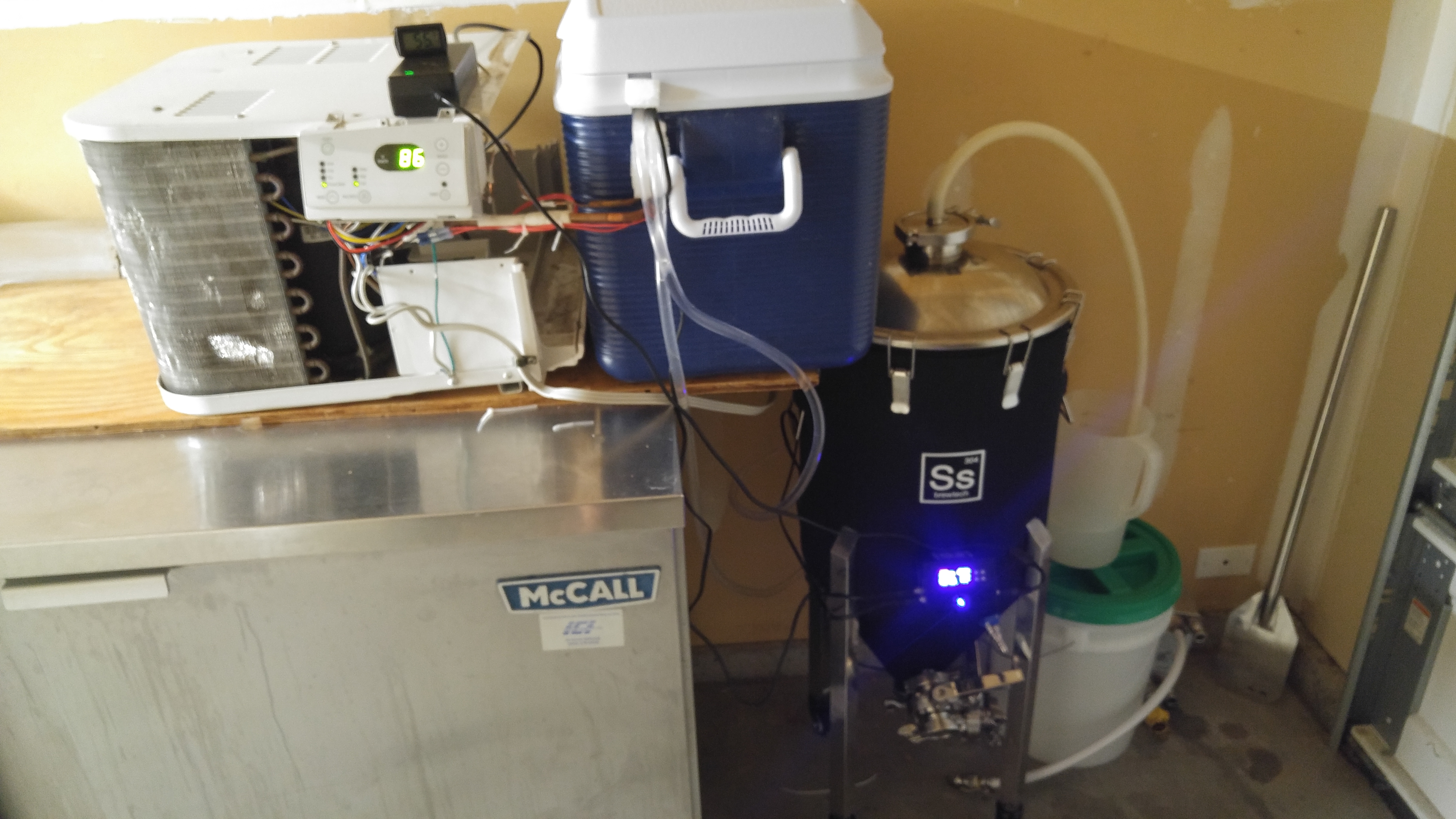
Recently purchased an SS Brew Tech Conical Fermenter and was looking to do a DIY Glycol chiller setup.

My buddy had a 6K BTU window AC unit collecting dust he was going to pitch, and was gracious enough to donate to the cause.

The unit has full digital controls:
Three fan speeds, fan only, Energy Saver mode, Auto, Cool.

My intent was to use a spare A419 on this unit, but that dream quickly evaporated when I took it apart.

Challenges:

Three speed fan → three 12v relays used to control fan speed. Controller has a build in trans former. Unit would not run with the fan speed wires disconnected.

Compressor would also not run without the fan speed wires connected. Did not attempt to re-wire unit to make this feature work. What's the point without a fan?

Temperature range on the digital display went from 64 - 86 deg. Not nearly cool enough to be used as a glycol chiller.

At this point I was starting to think I&#8217;d just shop for a cheap (<50$) Manually controlled unit but then something dawned on me. Why Couldn&#8217;t I use the existing controller, but just induce a temperature offset to the controller?

Solution:

Upon further inspection, I found the existing Thermistor used by the unit was a 30K variant (30k ohm reading at 25c) In general this is the HIGHEST you can get for most applications. This was a GOOD thing!

I compared the resistance readings of the different Thermistor types, and I quickly found that a lower resistance variante @ room temperature would induce the temperature offset I needed to use the built in controller.

To Explain:

Using a Thermistor resistance vs Temperature Chart, I found the existing Thermistor (30k ohm) read ~41k ohm - ~24k ohm at the ranges the controller would let you adjust too.

Using the SAME chart, I can see a 10K ohm Thermistor would net ~19.5 - 40 degrees @ the same resistance reading.

BINGO! Quick search on amazon (uxcell Waterproof Temperature Thermal Thermistor TC 10K Probe Sensor), 4$ later I have a new Thermistor in my hands ready to use.

Now I can use the built in controller on the Window AC unit and control my chiller water between 19.5 deg when set to 64, and 40 deg when set to 86.

If you find a killer deal on a digital window AC unit, before you pass it up or spend more on a mechanically controlled one. Consider this as a solution.

YskDH7R.jpg
 
My LG portable a/c unit has 2 thermistor's going to one connection. One was on the side of the cold side and the other directly in front of the cold side. Which one should I buy?
 
I'm reviving this post as I see it has been a few months since this was posted. I've asked a question in another thread as to whether I should work with an analog AC that I have or a digital one. Turns out that the digital one is exactly the same unit that you used!

Would you mind taking a look at my two options and suggesting which route I should go? Also, how difficult were the pipes to bend to get them into the cooler?
https://www.homebrewtalk.com/forum/...-a-glycol-chiller-build-which-is-best.652511/

Thank you!
 
Hey there my name is Kevin I recently built a glycol Chiller with an analog control system it was a lot easier to manipulate the thermostat so that I could use my inkbird thermostat. On the analog unit there are two wires connecting to the thermostat I disconnected them and splice them together so that once Powers applied it runs 24/7. So once connected to my inkbird that will control when it goes on and off. digital units are possible to hack for our purpose I'm just not Savvy enough in electrical engineering to figure it out.
 
I had a digital unit that I tried to use prior to my analog build. Once I disconnected the thermostat it wouldn't run. I gave up on digital units. My analog unit runs flawlessly.
 
The trick to the digital ones is to get rid of the digital control panel, circuit board and the two temp sensors. Mark all the wires and study the schematic that is on the housing. That leaves the compressor, capacitor, condenser fan & coil, and evaporator coil. I left the compressor and condenser fan and coil where they were originally on mine. Moved the circuit board/capacitor housing to the other side where there was vacant space and wired in an InkBird STC-1000 in the top of the cover housing. A Dremmel worked well for that. Bent the copper tubing with a tubing bender, very carefully!
 
Last edited:
The trick to the digital ones is to get rid of the digital control panel, circuit board and the two temp sensors. Mark all the wires and study the schematic that is on the housing. That leaves the compressor, capacitor, condenser fan & coil, and evaporator coil. I left the compressor and condenser fan and coil where they were originally on mine. Moved the circuit board/capacitor housing to the other side where there was vacant space and wired in an InkBird STC-1000 in the top of the cover housing. A Dremmel worked well for that. Bent the copper tubing with a tubing bender, very carefully!

Hey Mike. I’m trying to do the same with a digital AC unit. However, I’d like to have it controlled with the Inkbird ITC-308. I need some help in figuring out how to rewire the existing setup so the fan and compressor come on at the same time whenever the Inkbird decides to turn it on. Here is my wiring diagram. Suggestions?
 

Attachments

  • 7777E4BD-F89B-40A3-9E6C-C52F9C369174.jpeg
    7777E4BD-F89B-40A3-9E6C-C52F9C369174.jpeg
    1.8 MB · Views: 320
The trick to the digital ones is to get rid of the digital control panel, circuit board and the two temp sensors. Mark all the wires and study the schematic that is on the housing. That leaves the compressor, capacitor, condenser fan & coil, and evaporator coil. I left the compressor and condenser fan and coil where they were originally on mine. Moved the circuit board/capacitor housing to the other side where there was vacant space and wired in an InkBird STC-1000 in the top of the cover housing. A Dremmel worked well for that. Bent the copper tubing with a tubing bender, very carefully!

Hey Mike. I’m trying to do the same with a digital AC unit. However, I’d like to have it controlled with the Inkbird ITC-308. I need some help in figuring out how to rewire the existing setup so the fan and compressor come on at the same time whenever the Inkbird decides to turn it on. Here is my wiring diagram.
 
Ok, I figured it out. I ended up supplying 110v to compressor as well as the red wire on the fan. Now the system runs full time whenever power is supplied.
 
Ok, I figured it out. I ended up supplying 110v to compressor as well as the red wire on the fan. Now the system runs full time whenever power is supplied.
Care to share how you did it? I'm getting ready to convert my digital one for a glycol system too and am stuck.
 
See attached wiring diagram.
I bypassed the circuit board by removing the black (BL) wire (from external plug) from the relay attached to the circuit board. This removes all power to the circuit. Next I yanked the blue common wire (BL) from the same relay. If you connect these two, you’re compressor is now operational without the digital controller. For the fan, I cut the black wire (BK) at the relay attached to the circuit board hi fan setting and attached it to the bundle created for the compressor (3 wires splices together). Ops tested for power to the fan and compressor. For the thermostat, It was two wires to one probe. I cut the probe off and made a loop. Every other wire was kept in place. Now I’ll plug it into a two controller and work on the cooler side of things.
 

Attachments

  • Wiring Diagram.pdf
    92.5 KB · Views: 352
See attached wiring diagram.
I bypassed the circuit board by removing the black (BL) wire (from external plug) from the relay attached to the circuit board. This removes all power to the circuit. Next I yanked the blue common wire (BL) from the same relay. If you connect these two, you’re compressor is now operational without the digital controller. For the fan, I cut the black wire (BK) at the relay attached to the circuit board hi fan setting and attached it to the bundle created for the compressor (3 wires splices together). Ops tested for power to the fan and compressor. For the thermostat, It was two wires to one probe. I cut the probe off and made a loop. Every other wire was kept in place. Now I’ll plug it into a two controller and work on the cooler side of things.
Thanks for the info! I'm still waiting on the wire diagram on my model ac unit. Fingers crossed that I don't botch this one.
 
IMG_1600.JPG
IMG_1591.JPG
IMG_1602.JPG
[
IMG_1592.JPG
View attachment 637379

I don't know if this helps anyone, but I just built a cooler out of a remote only window unit I was given without the remote. I was a long way to figuring how to run it when it occurred to me I did not need anything but the 120V circuitry. I removed everything but the compressor, fan and capacitor. For the multi speed fan, I just hooked up the high speed wire and way it went.

Tucked under fermentor table and ready to hook up.
 
Last edited:
I know this is an older thread, but it's relevant to my current needs. I need help bypassing all the digital stuff. I have a vague idea of which wires to cut, but want to be sure. Also, do I need the capacitor, or does that get bypassed as well? I can take more pics if necessary.

Here's the wiring diagram for the A/C:
IMG_3054.JPG


And here are a couple pics of the business:
IMG_3055.JPG

IMG_3056.JPG
 
Did you ever get help with this?

Yes you need the capacitor, it looks like you have a 3 speed fan motor controlled by relays. I would cut and cap the black and blue fan motor wires and splice the red into the black from your power cable. Remove the blue wire on the common side of the capacitor it won't be needed it provides power to the board and transformer which you will be getting rid of. Wire your temp controller of choice in place of the compressor relay, you will need to splice a connection off the white wire to power the controller and place the temp probe inside the cooler. Everything else you should be able to get rid of. Sorry for the crap drawing I'm using my phone but I hope that helps.

20201226_213647.jpg


I know this is an older thread, but it's relevant to my current needs. I need help bypassing all the digital stuff. I have a vague idea of which wires to cut, but want to be sure. Also, do I need the capacitor, or does that get bypassed as well? I can take more pics if necessary.
 

Attachments

  • 20201226_213233.jpg
    20201226_213233.jpg
    390.5 KB · Views: 18
Did you ever get help with this?

Yes you need the capacitor, it looks like you have a 3 speed fan motor controlled by relays. I would cut and cap the black and blue fan motor wires and splice the red into the black from your power cable. Remove the blue wire on the common side of the capacitor it won't be needed it provides power to the board and transformer which you will be getting rid of. Wire your temp controller of choice in place of the compressor relay, you will need to splice a connection off the white wire to power the controller and place the temp probe inside the cooler. Everything else you should be able to get rid of. Sorry for the crap drawing I'm using my phone but I hope that helps.
Thanks for that! Works like a charm!
 
Back
Top