• Please visit and share your knowledge at our sister communities:
  • If you have not, please join our official Homebrewing Facebook Group!

    Homebrewing Facebook Group

TJTHEBEST's E-BIAB Build!

Homebrew Talk

Help Support Homebrew Talk:

This site may earn a commission from merchant affiliate links, including eBay, Amazon, and others.
Isnt the switch that PJ is showing a 3 way switch. So i could switch it between the timer/off/PID? If its like that it would be great. However, if im mistaken than i definitely want two switches.
You did good and are right on the money with your understanding of the diagram.

P-J
 
Thanks PJ!!

Do you think i could get a copy of that handy Brew parts order spreadsheet that ive seen floating around? I dont want to forget anything that i may need.
 
Do you mean this one?
(It is not configured for your set up.)

Click on the image to see the actual spread sheet.

--- Then save it to your system. The Excel file is not password protected so that you can add things that interest you. You can use the tab key (and back tab key) to navigate the sheet.


I Sure Hope This Helps You!

P-J
 
So with this configuration will the switch for the PID turn the Timer and the PID on? Or will the Timer be on the as long as the panel is plugged in?
 
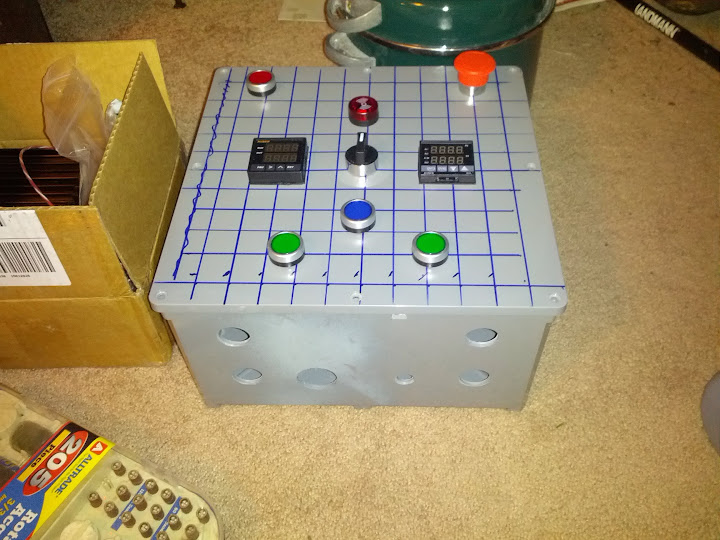
Also here is how im planning on laying out my control panel.

Any comments/concerns/suggestions would be greatly appreciated.

Control Panel Layout.jpg
 
So with this configuration will the switch for the PID turn the Timer and the PID on? Or will the Timer be on the as long as the panel is plugged in?
The way it's setup, the timer is on when the panel is plugged in.

I can change that for you if you want. (I suggest - Yes.)

Just let me know.
-----------

Nevermind.. I made a new diagram for you anyway (different name):

As always, click on the image for a full scale diagram printable on Tabloid paper (11" x 17")


P-J

(BTW - I discovered that I made a wiring error in the previous version. I fixed it now so if you have saved it you might want to refresh it to the version now up in this thread.)
 
what are you using as the control panel housing? The first order of parts arrived and the PID is longer than I expected so I need to locate new housing. Im building the same rig as this diagram to hold me over until Im ready to go do the 3 vessel system.
 
Thanks PJ!! You are always so darn helpful!

Olive Drab, I have a 12X12X6 NEMA box that i am planning to use. Though i might buy a project box from auberins. How deep is the is the one you have?
 
Possibly changing directions. After the whole 3/4 wire dryer debacle ive decided that maybe i should try a little bit safer of a way to do this.

I discovered i have one of those breakers that is a 20 amp breaker but has 2 of those switches on it. as shown in the picture with the breaker labeled service outlet.
IMG_20121211_172841.jpg


This feeds two receptacles that are right next to each other. My question is: Can i use those 2 receptacles in order to build a control panel with (2) 2,000 watt elements? What im unsure of is if these are 2 separate circuits.

This would be the wiring diagram that i would like to follow.
auberinwiring1a42000wbi.jpg


What say you all?
 
You want to use two separate 20 amp GFCI circuits to feed your panel.
Try this:
* Pick one outlet
* Turn off the breaker for this outlet
* Find another outlet that is still powered on, this is on a different circuit.
 
Just ordered all my auberins stuff and bought most of what i need to build 2 heatsticks. Now i just need to figure out if i can wire in a timer the same way as my original plan.
 
TJ,

Was reading this with great interest...until you had to go the other route. Maybe you can answer a few questions I have. You said you were going to go the recirc route, had you considered a RIMS set-up? Or, did you find this unnecessary with the element in place in the kettle? Here is a question I am searching for an answer to...why do you need to have a power switch to the PID, why can't it be on 100% of the time? IF there is no power to the Contactor, via a switch who cares if it sends a signal to the SSR? Just wondering.

I went with Recirc because its alot simpler than RIMS and does basically the same thing. The PID power switch is basically just a Unit on switch. Instead of it just turning on when i plug it in. This could be bad if you acidently plug it in while the elements are not in water.
 
P.J., if you're still following along, im trying to figure out how to add in a timer and the 3 way switch to the new diagram with the 2 elements. It seems to me, and i could be completely wrong, that there is several ways to wire in the timer/alarm/buzzer. It just seem like on the two diagrams that are up in this thread that you are using differing terminals.

If you could help me by updating the drawing with the 2 elements to add in a timer and a 3 way switch to switch between the timer alarm and PID alarm that would be great.
 
All my auberins stuff came. Well except for my emergency stop switch which i apparently forgot to order. I noticed that the EPO switch on the diagram i am using says to add another module switch box. My question is which one do i buy, an NO and/or NC?

thanks,

TJ
 
All my auberins stuff came. Well except for my emergency stop switch which i apparently forgot to order. I noticed that the EPO switch on the diagram i am using says to add another module switch box. My question is which one do i buy, an NO and/or NC?

thanks,

TJ

NO although i believe the Auber modual comes with NO and NC contacts

good luck
 
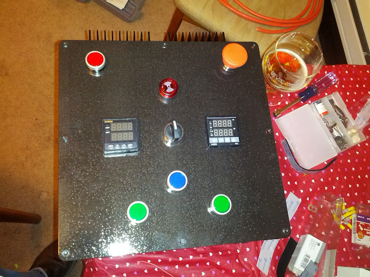
Well i drilled most of my holes and mounted the buttons and stuff on the front. Just need to dremel the square holes for the SSR's and heatsinks and figure out where to mount everything on the inside. Then its on to painting and wiring.

IMG_20130117_184902.jpg
 
It sure is tedious, but once you get going, it happens pretty quick. I like the paint job!

How are you wiring the timer in?
 
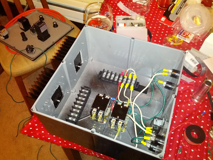
Well i finished all my wiring!!! Now i just need to troubleshoot my problems.

1. Element #1 does not fire. Must be some loose wiring somewhere between the ssr/contactor??

2. Element #2 Contactor is quite considerably louder than the other one. Might be a bad contactor??

Im getting my dads multi-meter tomorrow so i can check continuity throughout my system.


Everything else seemed to be working correctly!

IMG_20130126_191905.jpg
 
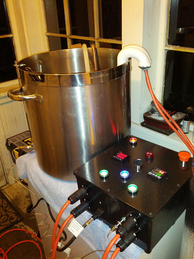
Hey TJ, the build is looking GOOD. Are those the switchcraft plug/receptacles? It looks like you have 4? Where do you have them going/coming from?

Corey
 
smittygouv30 said:
Hey TJ, the build is looking GOOD. Are those the switchcraft plug/receptacles? It looks like you have 4? Where do you have them going/coming from?

Corey

Halfway through his planning, he realized he couldn't do a 220V build. He changed gears and built two heatsticks pulling power from two separate circuits.

Soooo, he has two power feeds going into the panel and two lines going out to the kettle/heatsticks.

Hope that helps.
 
Halfway through his planning, he realized he couldn't do a 220V build. He changed gears and built two heatsticks pulling power from two separate circuits.

Soooo, he has two power feeds going into the panel and two lines going out to the kettle/heatsticks.

Hope that helps.

Exactly!
 
Well i believe that i have 2 faulty contactors... what are the odds? They both get 120 to the input side, both get 120 to the coil. One of them doesnt give power to the output side and one of them is really really loud.
 

Latest posts

Back
Top