• Please visit and share your knowledge at our sister communities:
  • If you have not, please join our official Homebrewing Facebook Group!

    Homebrewing Facebook Group

Suggestions on omitting swapping tubes

Homebrew Talk

Help Support Homebrew Talk:

This site may earn a commission from merchant affiliate links, including eBay, Amazon, and others.

Tobor_8thMan

Supporting Member
HBT Supporter
Joined
Feb 15, 2013
Messages
3,711
Reaction score
2,250
Location
Go 97 miles and take a right...
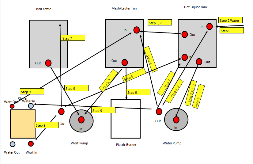
My setup follows. Any recommendations, suggestions, etc on omitting swapping tubes?
1630629697238.png
 
Why do you have the MT going into your bucket? What you're showing, to me, looks like a convoluted mess.

I only move a couple of hose connections during the brew day/process. For moving the wort from the MT to the BK (otherwise it goes through the HERMS coil), running the sparge water from the HLT into the MT. I move the hose that was going from the MT out to the pump in to the BK out. The hose that was going from the wort pump into the HERMS coil shifts to the whirlpool fitting on the BK. Then one hose change for the wort pump to the wort strainer that's in front of the plate chiller.

The water pump, in my setup, is recirculating the water in the HLT for most of the session. I only shift the water pump out to the HERMS coil inlet to add the sparge water to the MT. Then that connection goes back to the recirc connection. I'll have to double check, but I think I use a shorter hose for putting the sparge water through the HERMS coil (the recirc hose is a lot longer than it needs to be).

I don't use a pump to put the chill water through the plate chiller (why would you??). I simply connect the chill water source hose (from the utility room, very close to where I brew). The chill waste water hose runs out into the driveway.

I can take some pictures for each change when I brew Saturday.

I really think you need to review that drawing. There are paths that make zero sense. Why would you run the wort, post boil, through the MT? You also seem to have left out "step 8".
 
"I don't use a pump to put the chill water through the plate chiller (why would you??). I simply connect the chill water source hose (from the utility room, very close to where I brew). The chill waste water hose runs out into the driveway. "

The counterflow chiller works best with a pump.

I don't waste water. The hot water from chilling is used for other purposes.
 
The MLT drains to the bucket at the end of the whole deal. I presume the bucket is his fermenter. What's more interesting is why he has his PC wort-out feeding the MLT to begin with. Seems to me chilled wort could go straight into the bucket and skip the MLT.

I run a 3V2P herms and I reckon if I diagrammed the full brew day from loading and heating the strike and sparge volumes, underletting the strike, recirculating the mash, then performing the fly sparge, then post-boil recirculation including chilling with the IC, then lautering to the carboys, there are at least six hose configurations involved. So not all that much simpler than the above. One big difference is given the tons of post-boil hops I've been using for all the neipa's that have dominated my brewing the last three years I have been using my SS IC instead of my DudaDiesel 30 x 12 PC. So there's at least two hose set-ups I haven't been using of late - I go straight from the boil through the IC chilling then move the pump output to the carboys at the end...

Cheers!

[edit] wrt the chilling water source, the drawing certainly suggests it's pumped...
 
Wtf…I process mapped my 3 keggle + extra mash tun 10 gallon x 2 system 15 years ago and it wasn’t this complicated.
 
Have you thought about building a manifold with. An inlet and multiple outlets with a ball valve on each! It's what I do and love it. Just a thought. That does look like a PITA to deal with. Maybe add a grant to simply ???
Cheers
Jay
 
Have you thought about building a manifold with. An inlet and multiple outlets with a ball valve on each! It's what I do and love it. Just a thought. That does look like a PITA to deal with. Maybe add a grant to simply ???
Cheers
Jay

I was looking at that. There would need to be a manifold at every input or output that has more than one destination or more than one source. I count six manifolds and 15 ball valves.

There are some strange things going on. Step 9 is a mystery to me. Wort out of the boil kettle, into a pump, pumping wort through his wort chiller, out of the wort chiller, into the mash tun, out of the mash tun then into the plastic bucket?
 
Last edited:
@Jaybird any images or info for the manifold? I was thinking the same. Problems that come to mind. Where to attach the manifold (I have a SS brew table holding all the kettles). Also, I use QD on the ends of the hoses.
Not really sure without seeing your actual process. Likely you could optimize your process a tad to make things simpler. But like I said without actually having a full understanding of that process I couldn't say 100%. Just remember for every time you swap hose to the input side of the pump to the outfeed of the pump you'll need a ball valve. Personally I can't imagine needing more than 1 in and out per kettle per pump. So 3 in and 3 out per pump. 12 valves? Then optimize your process from there. Do you use both pumps for every kettle? If not at that spot you eliminate a ball valve.
Hope that helps.

Cheers
Jay
 
My plate chiller chills best running off the water directly from the highest flow faucet I have (from the utility room). This gives me a chill times in the sub 10 minute range, even for 13-14 gallons going into fermenter. My 'normal' 7.5-8 gallon batches (into fermenter) are less than six minutes to chill to pitch temperature. I run the chill water at max flow/speed and control the flow of the wort out of the plate chiller. Easily getting the batch to about 65F at the end of the transfer.

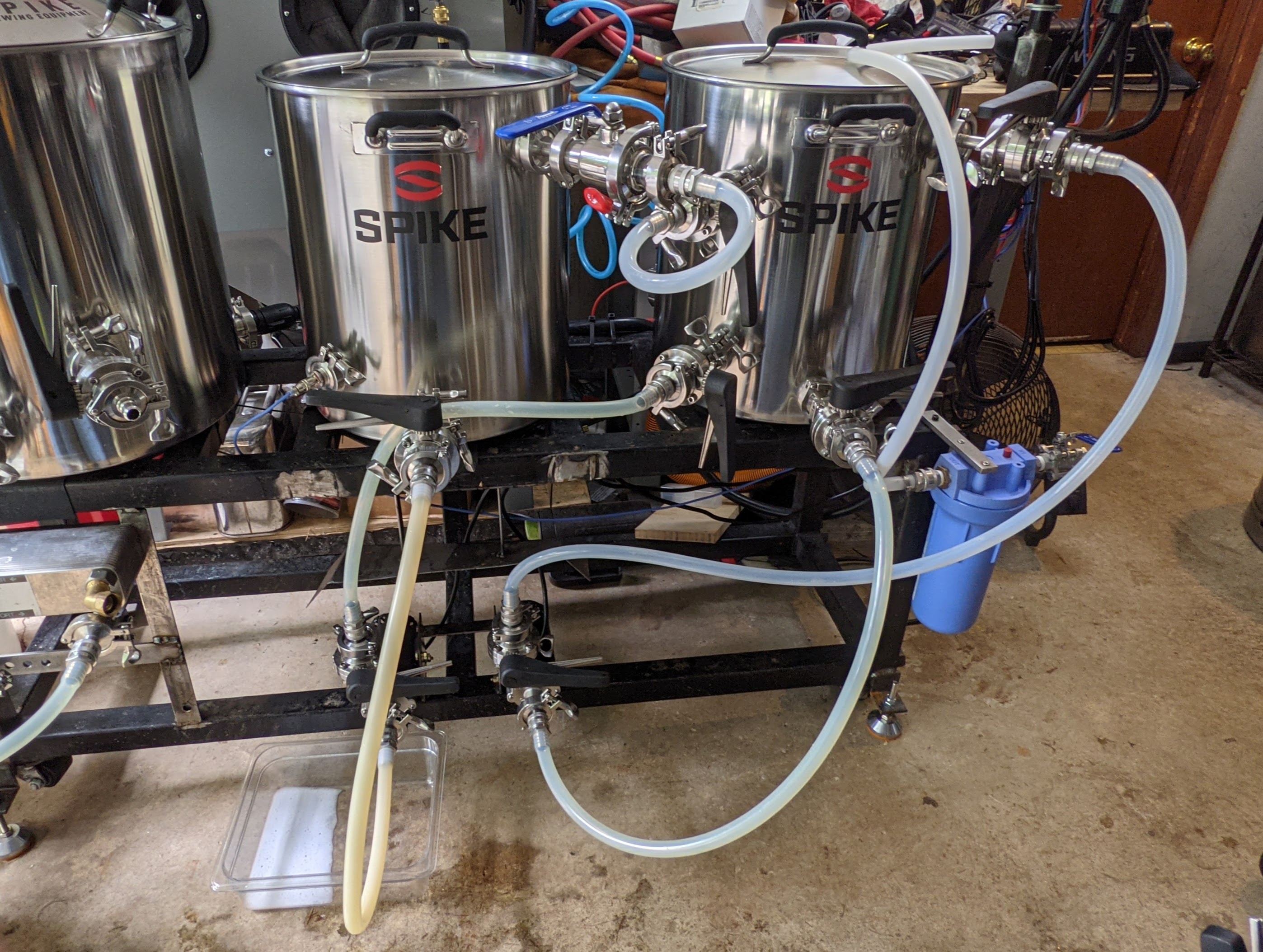
For the tubing, I change where a couple connect during the process. But no where near what you have mapped out. This picture shows my MT and HLT plumbed up for use.
PXL_20210903_185615620 (1).jpg


I don't have my wort strainer/filter in position since it's not brew day. But, that is simply changing the BK whirlpool line from the wort pump (the one on the left) to the strainer inlet. The strainer out port goes to the chiller inlet and the then chiller out has a TC connection to my wort flow control valve and O2 oxygenation kit setup. That then runs into the conical connection (either bottom dump or racking arm) to put the chilled wort in. I only change a couple of hoses (max) during the process. I will move connections as needed. Mostly the wort pump inlet between the MT and BK and the wort pump out from the HERMS coil in to the BK whirlpool fitting. Plus the HLT recirc line shifts to either the HERMS inlet or the MT recirc fitting when adding sparge water.

IMO, if you're changing a lot of connections around, then you either need a manifold (or a few of them) or you need to rethink your process.

For the record, I'm on a well for water, so very little need to try to minimize the amount of water used by the plate chiller. Since I have zero expense when it comes to water to the house. IMO, If you are charged so much per gallon of water used that it hurts to brew with efficient chill rates, then there's other things you need to look at. Even when I was on city water, I didn't really notice any change in my water bill for when I brewed. Or at least not enough difference to matter.

Also I'm calling BS on "The counterflow chiller works best with a pump." Simple thermodynamics impact both CFC and plate chiller rates and such. The faster/more cold water you have running against the hot wort, the higher your wort chill rate will be. If you're getting slow chill rates either way, then time to consider getting an efficient wort chiller.

I do use whatever water is left in my HLT (I fill it almost completely for each brew no matter how much I use so that the HERMS coil is fully submerged) to mix up PBW to use in the BK, plate chiller and wort pump cleaning.
 
If you want to keep all the water & wort paths as shown in your diagram, and do not want to be swapping hoses around, the only solution is see is a combination of water/wort splitters and sums used in concert with a combination of Open/Close valves.

You can make the splitters/sums from a combination of NTP piping material, stainless steel, high temp PVC, brass, etc. You might use copper pipes and solder together you laberynth of water & wort paths. I cannot imagine that there are many off the shelf parts to get where you want to nd up.

Example, the output of your water pump has four possible destinations. How do you satisfy that requirement? You take the output of the water pump, split it 4 ways such that it can feed 4 different Open/Close valves. When you are executing a given step, you open one of the four valves (as is appropriate) and the other three valves are closed.

On your hot liquor tank, bottom left input, there are two possible sources for that input. Install a "Y" pipe in such that two sources can push liquid into that input. if you have two Open/Close on valves on the Y, one valve would be open, one would be closed.

It would not be hard to draw it up like an electrical schematics with switches in place of valves.

The logistics of plumbing this up would a challenge. And probably make for an expensive homebrew project. During your brew day, you would have to manage the coordination of the valves in the correct combination of open and close position as you go from one step to the next. If you made an error, who knows what the outcome might be.

If you went with voltage controlled valves, you could simplify your life. Many ways to open and close your valves in the right combinations. How is your budget for that? Maybe some brewery control software might be in order?

I will follow this thread to see the path you take.
 
@RufusBrewer possible to see photos or links to items mentioned in your post? Thanks.

NPT = National Pipe Thread. Home breweries are almost all be 1/2" NPT thread. It is a series of plumbing pieces that have male for female threads and you screw them together. Make sure you use a generous amount of Tefllon tape. You can purchase a combination of pipe, nipples, T-connections, cross and elbows.

Examples
A T-connection you can ma a 2x1 (splitter) or a 1x2 (Y connection).
A cross connection can make a 3x1 or a 1x3
To make a 4x1 or 1x4 you will have to get creative.

The pipe material of choice in a home brewery is stainless steel. There are also brass fittings. If you want to see what I am talking about, Home Depot and Lowes carries different NPT pipes fittings. I doubt you will find stainless steel at HD or Lowes. But you can get a feel for how NPT parts fit together.

McMaster Carr is an excellent resource to see what is available, and their prices are good enough to give you some budget numbers.

Check out the McMaster page below. It is a good place to start.

https://www.mcmaster.com/standard-pipe-fittings/pipe-size~1-2/
Scroll down the left side to see the Shapes section.

Here is stainlessbrewing's page on what they have to offer.

https://www.stainlessbrewing.com/Threaded-fittings_c_1.html
Other choices are copper plumbing up your system. Instead of threads to hold components together, you solder various T-connections, cross connections, elbows and bends. A trip to Home Depot will give you more insight than I can.

An alternative to copper is High temp PVC. PVC is easy to cut and basically you glue it together.

At some point you are going to decide how to control all the input and outputs. Select some sort of valve design. Manual valves come to mind first. referring to your Step diagram, you will have to come up up with some way to reconfigure your rig to satisfy a given step. Example: All valves closed, except Valve 1, 4, 5, 8 & 12 open.

https://www.dudadiesel.com/search.php?query=SSvalve
They voltage controlled valves are an option. That would be fun to figure out how to control 15 electric valves. Sorry, I am not much help on electric control valves. Here is a page to get you started.

https://www.dudadiesel.com/search.php?query=zerop
I expect that you will end up mounting the various fitting and valves on hunks of plywood, with pipe or tubing connecting to the kettle and pump ports. You do not want a bunch of piping hanging off you kettle port and applying diving board like stress on the fitting.

I would invest in quick disconnects and silicon tubing (not hard plumbing) to connect longer runs, like pump to kettle. I want ti see water and wort moving.

Where to get stuff? You are going to be buying up a bunch of parts and materials. Shop around, buy in bulk, get quantity discounts. Try eBay and Alibaba to see what you can get at reduces prices.

Hope this helps.
 
Back
Top