You are using an out of date browser. It may not display this or other websites correctly.
You should upgrade or use an alternative browser.
You should upgrade or use an alternative browser.
Stc-1000+
- Thread starter alphaomega
- Start date

Help Support Homebrew Talk:
This site may earn a commission from merchant affiliate
links, including eBay, Amazon, and others.
alphaomega
Well-Known Member
- Joined
- Jul 10, 2013
- Messages
- 1,041
- Reaction score
- 461
I got a message back. Seemed to be a miss pick. A refund has been offered so false alarm sorry")
Cool. I don't know how AliExpress works, but I thought they didn't 'stock' items for the sellers, just relayed sales. But that might not be the case then.
Göad you got it sorted.
I got a message back. Seemed to be a miss pick. A refund has been offered so false alarm sorry
It's not a false alarm if it happened to others too.
Glad you got a refund.
Fingers crossed the 2 I recently ordered turn out to be genuine.
View attachment ImageUploadedByHome Brew1450074730.140944.jpg
View attachment ImageUploadedByHome Brew1450074749.082790.jpg
The LEDs arrived today on the slow boat.
It works so I'm happy about that. I can now box this one up. I'm going to pass this one on to a homebrewing friend from work. .... Right after my next A400 arrives and I can get a proper 10k SMD resistor soldered on. [emoji1]
januzz
Member
Hi,
I have built an electrical BIAB /RIMS system with a 70 Liter kettle and a brewcontroller with your STC1000+ firmware.
We have been brewing 200 Liters now and i'm trully amazed how great the OVBS firmware is working. I't really amazing and i want to thank you for the great work on this!!
I was wondering if it is possible to use more than 4 Hop Alarms, since we only use 2 or 3 maish steps but 5 or 6 hops. Is it possible to have some less maisch steps and more hop alarms? Thanks
Keep up the great work!
Jan
alphaomega
Well-Known Member
- Joined
- Jul 10, 2013
- Messages
- 1,041
- Reaction score
- 461
Hi,
I have built an electrical BIAB /RIMS system with a 70 Liter kettle and a brewcontroller with your STC1000+ firmware.
We have been brewing 200 Liters now and i'm trully amazed how great the OVBS firmware is working. I't really amazing and i want to thank you for the great work on this!!
I was wondering if it is possible to use more than 4 Hop Alarms, since we only use 2 or 3 maish steps but 5 or 6 hops. Is it possible to have some less maisch steps and more hop alarms? Thanks
Keep up the great work!
Jan
Cool, glad you like it
Possible, yes, but I don't think I will add it.
There will always be someone wanting more of this and less of that, no matter what the number is.
Personally, I think 4 is too much
60 min and 5 min hop additions are enough in my book.

$53.24
1pc Hose Barb/MFL 1.5" Tri Clamp to Ball Lock Post Liquid Gas Homebrew Kegging Fermentation Parts Brewer Hardware SUS304(Liquid Hose Barb)
Guangshui Weilu You Trading Co., Ltd


$10.99 ($31.16 / Ounce)
Hornindal Kveik Yeast for Homebrewing - Mead, Cider, Wine, Beer - 10g Packet - Saccharomyces Cerevisiae - Sold by Shadowhive.com
Shadowhive
$53.24
1pc Hose Barb/MFL 1.5" Tri Clamp to Ball Lock Post Liquid Gas Homebrew Kegging Fermentation Parts Brewer Hardware SUS304(Liquid Hose Barb)
yunchengshiyanhuqucuichendianzishangwuyouxiangongsi


$28.98
Five Star - 6022b_ - Star San - 32 Ounce - High Foaming Sanitizer
Great Fermentations of Indiana


$76.92 ($2,179.04 / Ounce)
Brewing accessories 1.5" Tri Clamp to Ball Lock Post Liquid Gas Homebrew Kegging Fermentation Parts Brewer Hardware SUS304 Brewing accessories(Gas Hose Barb)
chuhanhandianzishangwu


$33.99 ($17.00 / Count)
$41.99 ($21.00 / Count)
2 Pack 1 Gallon Large Fermentation Jars with 3 Airlocks and 2 SCREW Lids(100% Airtight Heavy Duty Lid w Silicone) - Wide Mouth Glass Jars w Scale Mark - Pickle Jars for Sauerkraut, Sourdough Starter
Qianfenie Direct


$159.50 ($26.58 / Count)
3M High Flow Series System BREW120-MS, 5616001, For Brewed Coffee and Hot Tea, Valve-in-Head Design
Amazon.com


$58.16
HUIZHUGS Brewing Equipment Keg Ball Lock Faucet 30cm Reinforced Silicone Hose Secondary Fermentation Homebrew Kegging Brewing Equipment
xiangshuizhenzhanglingfengshop


$7.79 ($7.79 / Count)
Craft A Brew - LalBrew Voss™ - Kveik Ale Yeast - For Craft Lagers - Ingredients for Home Brewing - Beer Making Supplies - (1 Pack)
Craft a Brew


$20.94
$29.99
The Brew Your Own Big Book of Clone Recipes: Featuring 300 Homebrew Recipes from Your Favorite Breweries
Amazon.com


$44.99
$49.95
Craft A Brew - Mead Making Kit – Reusable Make Your Own Mead Kit – Yields 1 Gallon of Mead
Craft a Brew


$479.00
$559.00
EdgeStar KC1000SS Craft Brew Kegerator for 1/6 Barrel and Cornelius Kegs
Amazon.com


$22.00 ($623.23 / Ounce)
AMZLMPKNTW Ball Lock Sample Faucet 30cm Reinforced Silicone Hose Secondary Fermentation Homebrew Kegging joyful
无为中南商贸有限公司


![Craft A Brew - Safale BE-256 Yeast - Fermentis - Belgian Ale Dry Yeast - For Belgian & Strong Ales - Ingredients for Home Brewing - Beer Making Supplies - [3 Pack]](https://m.media-amazon.com/images/I/51bcKEwQmWL._SL500_.jpg)


$719.00
$799.00
EdgeStar KC2000TWIN Full Size Dual Tap Kegerator & Draft Beer Dispenser - Black
Amazon.com


$176.97
1pc Commercial Keg Manifold 2" Tri Clamp,Ball Lock Tapping Head,Pressure Gauge/Adjustable PRV for Kegging,Fermentation Control
hanhanbaihuoxiaoshoudian
januzz
Member
You're right Alphaomega, theres always someone who wishes something different. No problem
thx !
Jan
thx !
Jan
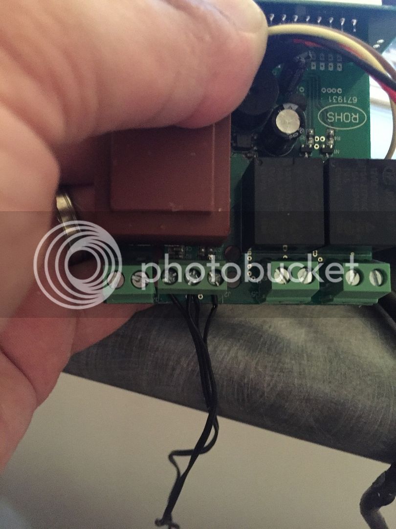
I got 2 more flashable A400_P versions of the STC 1000 today.
It is very possible to solder in the flea sized SMD resistors and get a 3 pole terminal soldered in.
Here is the temp of probe 1.
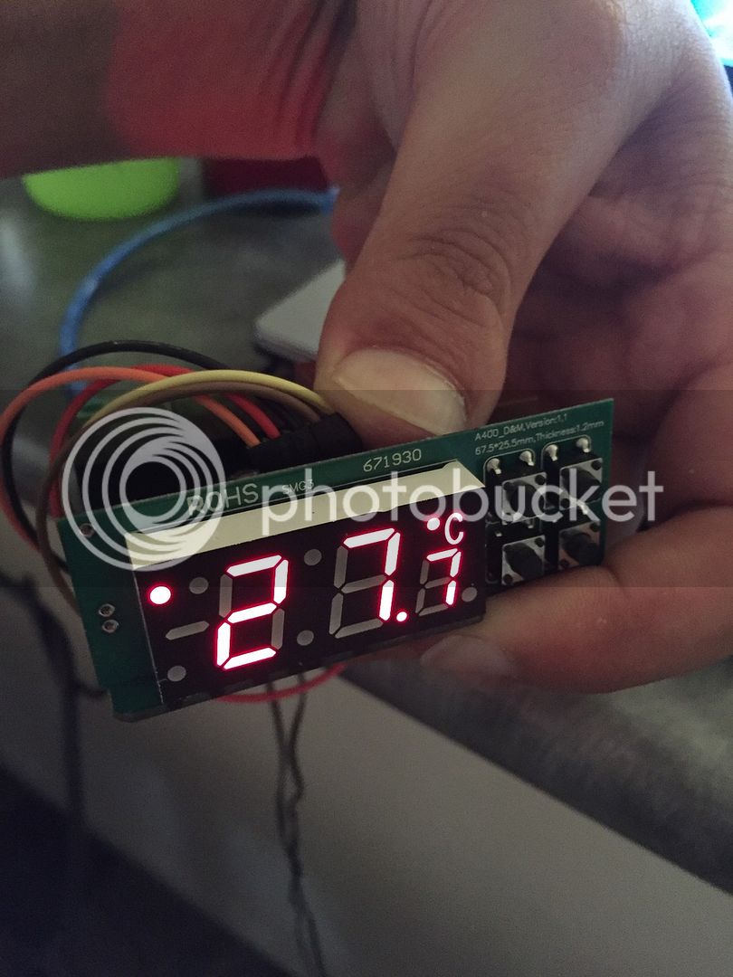
Here is the temp for probe 2.
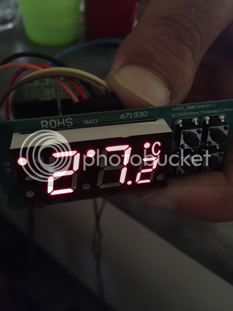
A much cleaner way to do it.
It is very possible to solder in the flea sized SMD resistors and get a 3 pole terminal soldered in.
Here is the temp of probe 1.
Here is the temp for probe 2.
A much cleaner way to do it.
hello all, is this the Arduino UNO that would be used in the no solder method to update the STC 1000?
http://www.amazon.ca/dp/B008GRTSV6/?tag=skimlinks_replacement-20
using the dupont cables, and header?
TIA
http://www.amazon.ca/dp/B008GRTSV6/?tag=skimlinks_replacement-20
using the dupont cables, and header?
TIA
Last edited by a moderator:
alphaomega
Well-Known Member
- Joined
- Jul 10, 2013
- Messages
- 1,041
- Reaction score
- 461
@A50SNAKE : Sure, that should work just fine
@A50SNAKE : Sure, that should work just fine
thank you soo much for your help.
a little bit more expensive then what I thought I saw on the project page, LOL....but that's pretty typical for cross border prices.
alphaomega
Well-Known Member
- Joined
- Jul 10, 2013
- Messages
- 1,041
- Reaction score
- 461
Well, that is probably a genuine UNO. If you check eBay, you can find very cheap clones, but you'll have to wait for the slow boat.
Well, that is probably a genuine UNO. If you check eBay, you can find very cheap clones, but you'll have to wait for the slow boat.
yes, that makes sense...thanks for all of your help and support.
I got the LED attached to this new unit and wired up the Arduino Nano. I used a couple of zip ties for tension relief on the wires. I also put a Bat85 Schottky diode on the 5V wire.
A little tidy up with some heat shrink and it will be ready to go in the box.
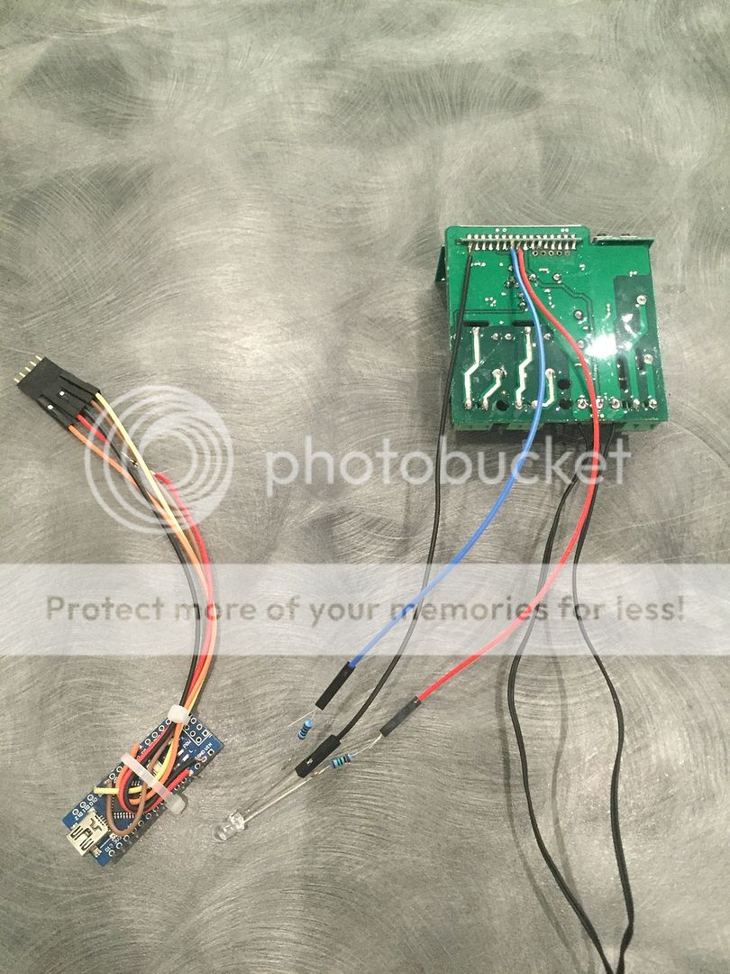
A little tidy up with some heat shrink and it will be ready to go in the box.
Hi,
I have built an electrical BIAB /RIMS system with a 70 Liter kettle and a brewcontroller with your STC1000+ firmware.
We have been brewing 200 Liters now and i'm trully amazed how great the OVBS firmware is working. I't really amazing and i want to thank you for the great work on this!!
I was wondering if it is possible to use more than 4 Hop Alarms, since we only use 2 or 3 maish steps but 5 or 6 hops. Is it possible to have some less maisch steps and more hop alarms? Thanks
Keep up the great work!
Jan
@januzz - I would love to see some pictures of your STC BIAB electrical panel buildup. I've been considering trying to build something as well but haven't found much for inspiration
Well, that is probably a genuine UNO. If you check eBay, you can find very cheap clones, but you'll have to wait for the slow boat.
@alphaomega - Hi Mats, I'm having trouble uploading the most recent picprog.ino to my Uno clone (CH340). I open the file and place it into a new folder, then hit upload and I get a series of errors - mainly 'get_device_id' was not declared in this scope. I am not connected to the STC, just connected directly to the Uno. Do you have any suggestions for this problem? I recall the first controller I flashed went flawless. I am using Windows 10 and the driver for the Uno seems to be installed properly as I'm able to send the 'Blink' function. Perhaps I'm selecting the wrong picprog.ino file? I'm just looking to flash the basic Vanilla version. Thank you in advance and Merry Christmas!
alphaomega
Well-Known Member
- Joined
- Jul 10, 2013
- Messages
- 1,041
- Reaction score
- 461
Hi @CNevay !
I saw your github issue, and that you already solved this (by downgrading your Arduino IDE). I don't know if it is an issue with the code with newer arduino IDE's or what. If that is the case, then I guess more ppl will eventually stumble on the same issue and I'll have to get it fixed
Anyway, glad you got it working and a holly, jolly, ho, ho, ho to you!
Hey there,
I have received the correct unit from U-control but keep getting the message "STC-1000 NOT detected. Check wiring." I have double checked the wiring multiple times and checked connections with a multimeter. The only thing im doing different than the instructions is using a Digix http://digistump.com/products/50 instead of an arduino. Could this be the issue?
Secondly when I run the software I had to increase the delay below before the initial message would appear. I have also played with the baud rates to no avail
Serial.begin(115200);
delay(2000);
Serial.println("STC-1000+ firmware sketch.");
Serial.println("Copyright 2014 Mats Staffansson");
Serial.println("");
Serial.println("Send 'd' to check for STC-1000");
Any advice would be much appreciated
alphaomega
Well-Known Member
- Joined
- Jul 10, 2013
- Messages
- 1,041
- Reaction score
- 461
@hidara: That looks like a sweet board, I haven't heard of it before (but tbh it is a bit pricey).
You are treading into the unknown, so I think you are on your own here. These are ARM boards I take it, so there is no guarantee that it will work, but being Arduino compatible does increase the the odds.
Just looking at the page you linked to, it clearly states that these are 3.3v devices. You should not connect 5v on the I/O pins! From your pics it seems you have. Unfortunately this could mean you may have damaged your board. Specifically, you may have damaged some of the I/O pins.
You could try and feed the STC with 3.3v instead of 5v. I have done so and it works fine. This could allow you to use this board. You might need to use other pins if they have been damaged. You may also want to add a resistor of a couple hundred ohms between the stc and dev board on the ICSPDAT line (and possibly ICSPCLK) to protect the dev board.
Good luck!
lockrob2000
Member
- Joined
- Jun 24, 2014
- Messages
- 12
- Reaction score
- 1
Is there a flash like this for the itc-1000?
or what is the chance that this flash would work on that model?
or what is the chance that this flash would work on that model?
alphaomega
Well-Known Member
- Joined
- Jul 10, 2013
- Messages
- 1,041
- Reaction score
- 461
Is there a flash like this for the itc-1000?
Not that I know of.
lockrob2000 said:or what is the chance that this flash would work on that model?
There is no chance. It won't work.
I'm trying to upload the sketch to my newly purchased Arduino UNO and I receive this error message, I'm new to this...so hopefully its just something I'm doing wrong, nothing major...but hoping someone can help me out:
picprog:190: error: 'get_device_id' was not declared in this scope
get_device_id(&magic, &ver, &deviceid);
^
exit status 1
'get_device_id' was not declared in this scope
I set the comport that the drivers displayed.
it was already set to the arduino UNO.
and that was all I did...I saved the vanilla sketch, exactly as it was. I tried to keep it simple...
thanks in advance for any help.
UPDATED:
see my post below. I am leaving this one up, as it shows the entire error message in case anyone else searches for that down the road.
Last edited:
Hi @CNevay !
I saw your github issue, and that you already solved this (by downgrading your Arduino IDE). I don't know if it is an issue with the code with newer arduino IDE's or what. If that is the case, then I guess more ppl will eventually stumble on the same issue and I'll have to get it fixed
Anyway, glad you got it working and a holly, jolly, ho, ho, ho to you!
Hi, I am also getting the same message, can I please know which version of the IDE worked to properly load the sketch file to the UNO?
thanks,
UPDATE:
OK, I was able to download and install the 1.6.4 version of the IDE software, and it was able to load it without any errors. just in case anyone else has the same issues as me.
http://arduino.cc/download.php?f=/arduino-1.6.4-windows.zip
http://arduino.cc/download.php?f=/arduino-1.6.4-windows.exe
Last edited:
alphaomega
Well-Known Member
- Joined
- Jul 10, 2013
- Messages
- 1,041
- Reaction score
- 461
Ok, so it seems something has changed with newer versions of the Arduino IDE.
Thanks for reporting this. I'll look into it as soon as I have the chance.
Glad you got it working by downgrading though.
Cheers!
Thanks for reporting this. I'll look into it as soon as I have the chance.
Glad you got it working by downgrading though.
Cheers!
Mats, awesome work. Got mine installed and tested.
I am running the single probe setup. I noticed with this firmware the unit accepts a single temperature set point for both heating and cooling and a single hysteresis value? Is that right?
I am concerned temp. undershoots will start the heater which will result in an overshoot and so on .... What do you recommed?
In your documentation you recommend using a long heating delay to avoid oscillation, which is probably appropriate if fermentation is in progress and generating heat, but will not help much once complete?
I would much rather have two sets of SP and hy parameters, one for heating and one for cooling. Is there any reason you'd advice against this? (Beyond lack of EEPROM and flash memory)
Thanks
alphaomega
Well-Known Member
- Joined
- Jul 10, 2013
- Messages
- 1,041
- Reaction score
- 461
@p_p : Use a low wattage heater. A long heating delay is also good.
Once fermentation is complete, it doesn't matter as much. Doesn't matter if it takes an hour or a day to reach diacetyl rest temp. You just don't want to heat more than you have to.
This has been up for discussion before in this thread. Complexity is one thing, buy mainly, if you are trying to maintain a temperature, why would it be ok to differ more in one direction than the other? Use a larger hysteresis setting then, and set another temperature instead.
@hidara: That looks like a sweet board, I haven't heard of it before (but tbh it is a bit pricey).
You are treading into the unknown, so I think you are on your own here. These are ARM boards I take it, so there is no guarantee that it will work, but being Arduino compatible does increase the the odds.
Just looking at the page you linked to, it clearly states that these are 3.3v devices. You should not connect 5v on the I/O pins! From your pics it seems you have. Unfortunately this could mean you may have damaged your board. Specifically, you may have damaged some of the I/O pins.
You could try and feed the STC with 3.3v instead of 5v. I have done so and it works fine. This could allow you to use this board. You might need to use other pins if they have been damaged. You may also want to add a resistor of a couple hundred ohms between the stc and dev board on the ICSPDAT line (and possibly ICSPCLK) to protect the dev board.
Good luck!
Cheers for the advice. I've attached a photoresistor to the pins and I seem to be getting the same readings on these pins as I am getting on other pins. So finger's crossed that the board is fine!
Ive tried other pins and I seem to be getting the same result. I'm going to borrow a normal arduino from a mate but was just curious about the Vdd1 vdd2 vdd3 and the pins they were assigned. What are they?
Cheers
D
alphaomega
Well-Known Member
- Joined
- Jul 10, 2013
- Messages
- 1,041
- Reaction score
- 461
I took inspiration from another sketch that implemented a PIC programmer uing an arduino, but ended up rewriting pretty much all of it. That sketch used three digital pins to provide power for the target for programming (you need several pins to provide the needed current). I ended up just using the the 5v pin, as it makes wiring it easier (just point-to-point), but kept the ability use these pins to provide target power as well, if it for some reason should be needed.
Similar threads
- Replies
- 2
- Views
- 950
