Stc-1000+

Homebrew Talk - Beer, Wine, Mead, & Cider Brewing Discussion Forum

Help Support Homebrew Talk - Beer, Wine, Mead, & Cider Brewing Discussion Forum:

This site may earn a commission from merchant affiliate links, including eBay, Amazon, and others.
Alpha, wanted to say thanks again. I've been using the STC+ but only in limited way and finally ventured into profiles. The logging shows just how beautifully this thing operates (I also like it showing the frequency shift days 2-4 during exothermic fermentation). This has been just wonderful.

Thanks!
Glad you like it :) And thanks for sharing your experiences!
 
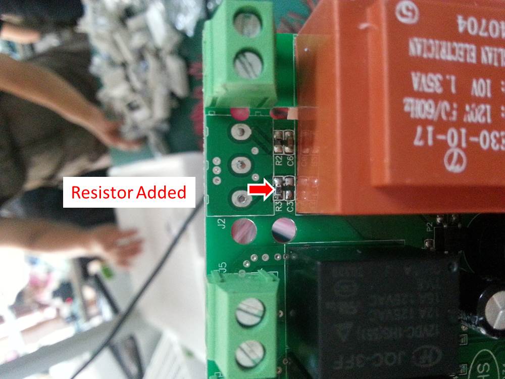
Some good news from the supplier I've been working with for these controllers; they were able to add a resistor and a 3-position terminal block to the board so that no physical mods will be needed in order to add the 2nd temp sensor. I've ordered 50pcs of these, along with 100 sensors, so will be offering them flashed w/ 2 sensors, ready to install, as soon as I receive them next week. Pics attached if you're interested.

ResistorAdded.jpg


3PosTerminal.jpg
 
Some good news from the supplier I've been working with for these controllers; they were able to add a resistor and a 3-position terminal block to the board so that no physical mods will be needed in order to add the 2nd temp sensor. I've ordered 50pcs of these, along with 100 sensors, so will be offering them flashed w/ 2 sensors, ready to install, as soon as I receive them next week. Pics attached if you're interested.

That my friend, is effing awesome... I can't tell you how sick I am of doing that manually, and I've only done 30 or so.
Big ups, Will!
Now, could you find some really cheap, 5pin, panel mount connector and corresponding plug with dupont connector in the other ends? :)
Right, now I'm choosing between RJ45 and and USB connectors. Really sick of soldering DIN connectors as well :)
Again, great work on getting that done! It would be really nice if they started doing that on all units produced :)
 
Alpha, one question.. I have programmed a few with just pressing the terminals together by hand. That works great, but if there is a glitch in the famus 20sec, will there be an error at the end? Asking another way, If the STC seems to operate correct and no error at end of programming is the programming ok then, or can there be a bad write?
 
Alpha, one question.. I have programmed a few with just pressing the terminals together by hand. That works great, but if there is a glitch in the famus 20sec, will there be an error at the end? Asking another way, If the STC seems to operate correct and no error at end of programming is the programming ok then, or can there be a bad write?

Believe it or not, but I dont really remember what happens if there is an error (ie connection is lost) during programming. At the least you will get an error message in the console, but I think programming stops also.
So, check the output in the console if you're not sure.
 
Some good news from the supplier I've been working with for these controllers; they were able to add a resistor and a 3-position terminal block to the board so that no physical mods will be needed in order to add the 2nd temp sensor. I've ordered 50pcs of these, along with 100 sensors, so will be offering them flashed w/ 2 sensors, ready to install, as soon as I receive them next week. Pics attached if you're interested.

Damn, I wish I had waited before buying two 1.0 units. Would you be willing to trade my two v1.0 units (still in the box/never used) for two of the 2 sensor units (plus your added costs of course)? Also, do your units have the header thing hardwired for future firmware upgrades?
 
Damn, I wish I had waited before buying two 1.0 units. Would you be willing to trade my two v1.0 units (still in the box/never used) for two of the 2 sensor units (plus your added costs of course)?

Sure, send me an email once I have the 2 sensor units in.

Also, do your units have the header thing hardwired for future firmware upgrades?

No
 
Tried that, no dice. They weren't able to figure it out and communication is difficult.

Sent from my iPhone using Home Brew

Bummer. Though, I could see some reasons as to why they wouldn't. To not 'contaminate' production line, they'd prolly have to do this by hand afterwards. And that might require a technician.

Its best to not get them to flash the controllers. SW control is retained here.

No. Having someone else doing the flashing will only mean less work. STC-1000+ is open, nothing is gonna change that.
 
mats (or anyone else who might be able to answer),
I'm attempting to try the dual sensor set up, but have a few questions.

1. I really don't want to try soldering the tiny SMD resistor. Will this resistor work?

2. If so, could I solder it remotely between GND and ICSPCLK at my MIDI panel connector that I use for flashing?

3. If that works for the resistor, could I still install a 3 terminal connector like this to connect the thermistor?

4. When using the 3 terminal connector for two thermistors, would they both share the center connection?

5. Am I correct that I should still be able to flash a unit set up like this without having to remove anything?

6. You reference connecting the thermistor between Vcc and ICSPCLK. I hadn't noticed it before, but in the pictures I believe it's shown as Vdd. Am I correct that these are one and the same?

I hope this all makes some sense as to what i'm trying to do. Once again, thanks so much for all the work you've done on this project. Hope that Mom and Baby are both doing well too.

Matt
 
1. Yes, but overkill. A regular 1/4W 1% will do.
2. Yes. As long as the resistor is between GND and ICSPCLK you're golden. Doesn't matter where it is physically located.
3. Yes.
4. Yes.
5. Yes.
6. Yes.

Thanks! We're all just fine. Just glad there isn't a zombie outbreak atm, 'cause we could easily be misstaken for the living dead about now :) *yawn*
 
1. We're all just fine. Just glad there isn't a zombie outbreak atm, 'cause we could easily be misstaken for the living dead about now :) *yawn*


Ah, I recall those days, some 18 years ago, so well! I wish I could tell you it gets better, but there always seems to be something, if only staying up to watch them sleep.
 
Thanks mats! Exactly what I was hoping to hear. I just ordered some 1/4W resistors. 200pcs delivered from China for a little over a buck. Seems like shipping would be that much! I'll have a bunch left over if anyone needs some.
 
If a Chinese company charges shipping it's just so they can get more money. Since the u.s. is in debt to china right now we have an agreement with then that any shipping to the u.s. is waived. If you go on eBay you'll notice that most Chinese sellers have free shipping. At most it should be a dollar.
 
Free shipping on ebay is a marketing tool. It doesn't mean the shipping literally doesn't cost anything. Or that the US government pays any and all shipping companies for it.
 
Just an observation. I buy a lot of stuff from china and it's not from eBay. I've also shipped things to china and I can tell you that it costs a hell of a lot more that a dollar.
 
What is the size of the SMD resistor needed? 1/4W 1%

The size is 0603. The ones I got were 1%, 0.1W and they've done nicely.
Ideally, you should probably try to match the resistor with the one already soldered in (measure them). Maybe you should even try to match the probes. I haven't, as I don't really consider the second probe all that important, but of the units I've done this far I've observed a difference of about 2F worst case, which I think is ok
If you have a multimeter, and get more than one resistor (which I think you pretty much have to, unless you recycle one), then I guess you might as well check a few resistors and see if you can find one that is a little closer.

Cheers!
 
So I went to check my keezer the other day and the temp was reading 86... i open it up and everything is frozen. After thawing, I put the temp sensor in a glass of ice water and it is reading 150... wtf? Anyone seen this before? Is it possible some buttons got hit when building it and I didn't notice or is the controller bad? Its the docooler version of this.
 
What firmware are you using? It is also possible the sensor is bad. Try another if you have one, if not they are super cheap on ebay. Either way it might be good to have a few as spares.
 
So I went to check my keezer the other day and the temp was reading 86... i open it up and everything is frozen. After thawing, I put the temp sensor in a glass of ice water and it is reading 150... wtf? Anyone seen this before? Is it possible some buttons got hit when building it and I didn't notice or is the controller bad? Its the docooler version of this.

Ok, so whatever happend, it is at least not my fault :) That is not an stc and it can't run stc-1000+.
Basically I know nothing about that one, but I've had weird stuff like that happen to other thermometers when moisture has gotten into the probe. That sucker might not be waterproof...
 
I know with some RTDs that only use 2 wires this can happen if you hook them up backwards. But I haven't ever heard of it with this kind of controller. Usually only with the pid type.
 
Yeah, I guess I should have noted that I had the thing dangled in a cup of water because I thought that is what everyone did to make sure the temp it read was more accurate to the beer temp but water most likely got in and killed it. I put an order on ebay for one but everything is from china and will be at least 2 weeks out. I don't mind paying a little more or making one if I could source the thing locally. Any ideas?
 
Are you looking for the standard black sensor for stc1000? 1 of the 50 controllers I received a week ago has a non functional speake so didn't build it into a full assembled unit. I was going to sell that unit flashed with 1.06 for 15 shipped. Didn't have any takers yet so I could donate the sensor from it to you.

Greg
 
If moisture is the problem (not that it is in any way confirmed), you can try heating the probe for an extended period of time and try to drive off the moisture. Some people have reported success with this (I haven't).
 
Are you looking for the standard black sensor for stc1000? 1 of the 50 controllers I received a week ago has a non functional speake so didn't build it into a full assembled unit. I was going to sell that unit flashed with 1.06 for 15 shipped. Didn't have any takers yet so I could donate the sensor from it to you.

Greg

Precisely that! Just shoot me a pm let me know how much to paypal you! Could probably drop it in a standard mail envelope and it would get here by the end of the week.
 
Precisely that! Just shoot me a pm let me know how much to paypal you! Could probably drop it in a standard mail envelope and it would get here by the end of the week.

No charge, just send me your address and ill ship it today :)

Greg
BrewsBySmith
 
Precisely that! Just shoot me a pm let me know how much to paypal you! Could probably drop it in a standard mail envelope and it would get here by the end of the week.

Ill send the controller w/1.06 software and temp sensor in case the sensor alone isn't your problem, don't want the halloween party suffering :mug:

Going out priority mail from Michigan today, you should receive it Wednesday. I will PM the tracking information to you in a second.

Greg
 
I've just done my first flash with the new software on a v1.0 STC-1000, and everything went very well. Basically, followed the instructions laid out by alphaomega supplemented with the video provided by wilconrad. I had a minor technicality getting the STC recognized by the "arduino" but after adjusting COM ports on the arduino it came to life. I used a cheap DCcduino "clone" board (i.e. not one that tries to fake Arduino brand) with CH340G instead of ATmega16U2, along with supplied drivers.

Here's my synopsis:
-NEW ATmega328P CH340G UNO R3 Board & Free USB Cable for Arduino DIY (ebay $6)
-40PCS Dupont wire Jumper Cable 2.54mm 20cm male - female 1P For Arduino uno R3 (ebay $2.90)
-STC-1000 v1.0 bought a while back from Amazon (~$20)
-Hand-held contact flash (as opposed to soldered header)

-Adjusted arduino COM port to 9 (COM 5 wasn't playing nice at all; for whatever reason, this change fixed connectivity issues)
-Make connections from arduino to STC, hold in place, plug arduino into PC via USB
-Start up arduino software, load image, upload to arduino
-Start Serial Monitor, adjust baud rate, hit 'd', hit 'f', wait 30 seconds
-Done!

Cheers to alphaomega and wilconrad for their detailed instructions!
 
Can I set custom Program when flashing instead of default. I would like to flash mine with my own setup instead of program trough buttons. Is that easy possible?
 
anyone actually kill a adruino uno? I flashed about 25 controllers tonight, and now the arduino won't come up as a com port, makes no difference to computer when I unplug and plug it back in, on multiple computers. USB cable seems to be okay checking continuity. Not sure what happened, but my flashing fun comes to an end about 25 controllers short :(

2 LEDs are lit up on the board, the ON green one, and a orange one with a L close to it.

Greg

Any chance you made a windows update?
FTDI has apparently made an indcredible a-hole move and in their driver that is pushed out with windows update, actually brick non genuine chips without ANY notification or anything! See this.

I really hope they bite the dust. I do understand they want to protect their IP, but this is so not the way to do it.
Anyway, if your arduino stopped working, it might well be due to a non genuine FTDI USB to serial chip.

If you have the choice, I'd strongly suggest avoiding FTDI (and windows for that matter).
 
Can I set custom Program when flashing instead of default. I would like to flash mine with my own setup instead of program trough buttons. Is that easy possible?

You can, but you need to recompile with your settings and build the sketch. The build script does this, but you need to run linux, and you'll need to install SDCC and GPUTILS. So yes, you can, but it will require you to setup a build environment.
 
Any chance you made a windows update?
FTDI has apparently made an indcredible a-hole move and in their driver that is pushed out with windows update, actually brick non genuine chips without ANY notification or anything! See this.

I really hope they bite the dust. I do understand they want to protect their IP, but this is so not the way to do it.
Anyway, if your arduino stopped working, it might well be due to a non genuine FTDI USB to serial chip.

If you have the choice, I'd strongly suggest avoiding FTDI (and windows for that matter).

No update, literally tried flashing one thirty seconds after the previous and it wouldn't work. The arduino I assume to be legit, paid 25usd for it from mouserr.com

I bought two more and have flashed another thirty controllers without any issue.
 
Any chance you made a windows update?
FTDI has apparently made an indcredible a-hole move and in their driver that is pushed out with windows update, actually brick non genuine chips without ANY notification or anything! See this.

I really hope they bite the dust. I do understand they want to protect their IP, but this is so not the way to do it.
Anyway, if your arduino stopped working, it might well be due to a non genuine FTDI USB to serial chip.

If you have the choice, I'd strongly suggest avoiding FTDI (and windows for that matter).
Quote From Hack A Day link above
The workaround for this driver update is to download the FT232 config tool from the FTDI website on a WinXP or Linux box, change the PID of the fake chip, and never using the new driver on a modern Windows system. There will surely be an automated tool to fix these chips automatically, but until then, take a good look at what Windows Update is installing – it’s very hard to tell if your devices have a fake FTDI chip by just looking at them.
 
Back
Top