• Please visit and share your knowledge at our sister communities:
  • If you have not, please join our official Homebrewing Facebook Group!

    Homebrewing Facebook Group

Stc-1000+

Homebrew Talk

Help Support Homebrew Talk:

This site may earn a commission from merchant affiliate links, including eBay, Amazon, and others.
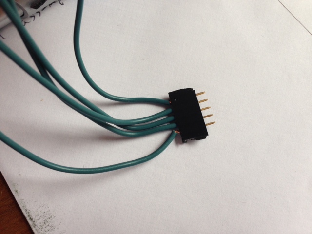
I have a couple old PC wiring harnesses laying around. Is there any reason I couldn't use one of the four wire connectors to solder in a permanent header to both the STC and the Arduino? That way you just clip it in if you need to flash. And, no cost.


Sent from my iPhone using Home Brew

One reason might be that you need 5 wires. You could get by with 4 if you allow target to supply power (i.e. skip 5v line and instead have STC-1000 provide power from mains), but you'll have to decide yourself if you are willing to do that (personally I would want to avoid it).
 
I was thinking it needed 3 wires, I think I got this project confused with another one. So as long as I can find a minimum 5 pin wiring harness I should be good.


Sent from my iPhone using Home Brew
 
I was thinking it needed 3 wires, I think I got this project confused with another one. So as long as I can find a minimum 5 pin wiring harness I should be good.


Sent from my iPhone using Home Brew

A USB cable would work, 4 wires, plus the shield at ground.
 
The ramp test is going beautifully and I have been running through shorter scenarios with a second unit. Haven't found any problems.

The only thing I might recommend, is for users to remember how the ramp function works (segments the step out into 8 even temperature changes). If you want a smoother transition over a long period of time, spread it across more than one step.

The last step in my test (not quite completed yet) is a 48 hour ramp from 68F to 33F. That gives me 4.375*F steps. If I were actually crashing something that I wanted a really smooth transition for, I would spread it across two steps and have 16 ramp changes (and 2.1875*F changes in this case, well it would round that to the tenth).

Just something to bear in mind.

Alpha, this thing is pretty awesome.

RampTest.jpg
 
The ramp test is going beautifully and I have been running through shorter scenarios with a second unit. Haven't found any problems.

The only thing I might recommend, is for users to remember how the ramp function works (segments the step out into 8 even temperature changes). If you want a smoother transition over a long period of time, spread it across more than one step.

The last step in my test (not quite completed yet) is a 48 hour ramp from 68F to 33F. That gives me 4.375*F steps. If I were actually crashing something that I wanted a really smooth transition for, I would spread it across two steps and have 16 ramp changes (and 2.1875*F changes in this case, well it would round that to the tenth).

Just something to bear in mind.

Disney, that is awesome! Great work! And great news!
I will try to be as clear as possible in the new user guide how ramping works, and its limitations and also suggest ramping over several steps if needed.

disney7 said:
Alpha, this thing is pretty awesome.

Ah, thanks man! That means a lot!
I truly hope somebody (besides myself) will find this firmware usable. And if I can just complete the user guide I'm thinking it is v1.0 time :)
 
I just flashed this onto my STC-1000 without any issue and am looking forward to putting it to use! FYI, I have no background in programming and had never used an Arduino prior to this, so the instructions have passed the idiot-test :)

Many thanks to Alpha, Disney and the rest of the developers collaborating on this effort! Awesome work.
 
Don't give me any credit, I'm just a mooch that has been testing and trying to poke holes in the thing.

I like your style Disney. As a European, we kind of have this notion of the typical American that is... well... let's say, not entirely positive. It is nice to know this is not true.
Though, I think you've earned your fair slice of the kudos pie. You have been extremely helpful! You and the other early adopters also deserve my thanks for daring to risk your controllers. Without you and your feedback I don't think the project would be where it is now. So, thanks!
 
Wilconrad, that is kewel! Atoughram mentioned wanting to do this; I was too worried about solder pad height diffs to try.
 
Don't give me any credit, I'm just a mooch that has been testing and trying to poke holes in the thing.

disney7, your testing/feedback has been awsomely helpful -- I am mostly hella-envious of the temp datalogging (BrewPi envy)
 
Wilconrad, that is kewel! Atoughram mentioned wanting to do this; I was too worried about solder pad height diffs to try.

I was a bit worried about the solder pad height issue as well, but I laid the pin header on it's side and pressed it against the contacts (like below); the pins will flex enough to take up any variation in the pad height. (also, the pads were pretty consistent in height, which helps).

Flash.JPG
 
I was a bit worried about the solder pad height issue as well, but I laid the pin header on it's side and pressed it against the contacts (like below); the pins will flex enough to take up any variation in the pad height. (also, the pads were pretty consistent in height, which helps).

wilconrad, would you mind if I 'steal' your picture to include in the user guide?
Edit: I'll credit you of course...
 
I have pushed a half-done copy of the user manual to the work branch (PDF format).
I'd very much appreciate any comments/corrections on the work on it so far.
English not being my native language, strange wordings etc. Basically, anything you think will improve it.
 
I have pushed a half-done copy of the user manual to the work branch (PDF format).
I'd very much appreciate any comments/corrections on the work on it so far.
English not being my native language, strange wordings etc. Basically, anything you think will improve it.

Looks great, Mats! I think your English is better than mine! :)
 
Has anyone started documenting this project? I've started on a operation and instruction manual but I dont want to duplicate the labor.

EDIT - Nevermind - I see there has been work on it! Thank You Alpha!
 
I have pushed a half-done copy of the user manual to the work branch (PDF format).
I'd very much appreciate any comments/corrections on the work on it so far.
English not being my native language, strange wordings etc. Basically, anything you think will improve it.

I look forward to reading it through. The instructions so far have been excellent. I had no issues with anything including getting and setting Arduino first time ever for flash. It really has been a very easy process.

EDIT: Alpha, PM'd you a couple VERY minor points. You really have done a SUPER job on this project!
 
I've been following this from a few days in, and I've been amazing at the progress - kudos to alphaomega for pulling something like this off! I'll be happy to supplement the field data as soon as I get some header pins for an arduino.

One quick question tho - if the thermistor lookup table is contained in the code on github, could it be exchanged with an appropriately formatted table for any other thermistor of 'type NTC (10K / 3435)'?

For instance, from vishay (where alphaomega pulled a 10k NTC thermistor table from as reference), there is this immersion sensor, which would be really cool to use for a RIMS temp sensor - may as well use both of alphaomega's awesome DIY projects together!
 
Well, I got in my Arduino and controllers today. I can confirm that both STC-1000's ordered from AGPtek are v1.0 and I got them in 2 days with Prime.

Being a complete n00b when it comes to Arduino, it was easy to get it installed and going. However, I'm also a n00b to github and was having issues trying to "download" the picprog.ino and open with IDE. I was trying to click on the actual picprog.ino file in the list but couldn't find a way to download. Then eventually realized that there was a download link for the whole package in .zip.

Soldering was easy enough, though I do have a decent amount of soldering experience. I did notice that the bottom of these boards seem to be coated with some type of clearcoat or plastic layer. I just melted through though and had no issues.
For those trying this, get a solder sucker and learn how to use it. It'll make your life easier!

Once I eventually figured out how to get the picprog.ino program into IDE properly, flashing was exactly as your instructions say. One word of the wise to those new to Arduino like myself, install the IDE software and USB drivers first from the Arduino site, then plug it in and make sure your computer detects it and make note of what COM port it's on. Being in IT for years I know this, but I also know many people wouldn't. Once you have the COM port, you'll want to make sure that your IDE software is set to that port (under tools - serial port).

So, I flashed one of the STC's and am just playing with the menus at this point. Definitely could use some updated instructions though as you'll likely want to print them out and leave them where they're handy when programming profiles.

Thanks alphaomega for all of your hard work on this! Hopefully I'll be able to find the time soon to run some tests for you and let you know the results.

Also, thanks to everyone else who gave info on the pin headers and cables. As my controllers are pretty well enclosed, I'm hoping to make it easy to plug and flash in the future if I need to without having to tear everything apart.
 
two new STC's flashed and one of them is controlling my beer refer now. :)

Please report back you experience. Even if you can't do logging, how does it 'feel'? Is it cycling too often? Does it keep temperature? Overshoots?
 
Being a complete n00b when it comes to Arduino, it was easy to get it installed and going. However, I'm also a n00b to github and was having issues trying to "download" the picprog.ino and open with IDE. I was trying to click on the actual picprog.ino file in the list but couldn't find a way to download. Then eventually realized that there was a download link for the whole package in .zip.

One word of the wise to those new to Arduino like myself, install the IDE software and USB drivers first from the Arduino site, then plug it in and make sure your computer detects it and make note of what COM port it's on. Being in IT for years I know this, but I also know many people wouldn't. Once you have the COM port, you'll want to make sure that your IDE software is set to that port (under tools - serial port).

These two points are exactly what I was going to mention for the instructions, in case anyone like me was GitHub/Arduino noob like me. The Arduino was really the only sticking point I had. I would recommend at least following through the BLINK LED "Hello World" equivalent program just to ensure you can figure your Arduino out. The second Arduino issue I had was my computer would "drop" the COM4 requiring simple USB cord unplug/replug. I think it has to do with the short SLEEP time or something but suddenly during testing I'd couldn't reflash as Arduino IDE complained about missing COM4. This is TOTALLY Arduino and my setup though, not AlphaOmega firmware.

Alpha, one minor point--when inputting settings on stock firmware, one presses PWR to fix the setting, and with STC+ setting a setpoint temp in a profile is fixed as soon as you up/dn to the temp, right?

Thanks alphaomega for all of your hard work on this! Hopefully I'll be able to find the time soon to run some tests for you and let you know the results.

Also, thanks to everyone else who gave info on the pin headers and cables.

I cannot emphasize enough how much everyone has helped me getting this setup, with nickmv, disney7, autograhm, and others. HBT rocks.
 
I hate to jump around (from the user manual draft), but I've been meaning to leave a desoldering tip.

A "solder sucker" works fairly well for me and is pretty much required if I'm desoldering something that already has a pin in it.

However, I've found the easiest way to clear the header through holes in the STC is to heat from the bottom of the board. Once the solder melts, quickly remove the iron and blow from the top of the board strongly. Most of the time you can blow all the solder out and have a perfectly clean solder pad.

You should wear safety glasses when doing this and be aware of where the blown solder is going to go (it usually cools before it hits the floor). You might also want to make a splash shield on the bottom of the board with painter's tape to prevent solder from possibly splashing onto the daughterboard pads, but I haven't had a problem with this.

Since this is not a professionally accepted desoldering technique, you undertake it at your own risk. Don't blame me if you burn something or your cat explodes.
 
Please report back you experience. Even if you can't do logging, how does it 'feel'? Is it cycling too often? Does it keep temperature? Overshoots?

I subbed my flashed controller out for another that was managing a lager I've got fermenting; it held at 50F through the evening without issue. Will be doing a diacetyl rest this weekend or early next week followed by a ramp down to 35 to test out the new ramping feature.

My setup is a thermowell inside a carboy, and I do experience some "ping-ponging" between 'heat' and 'cool'. This is not unique to the new code, though, I had this problem with the old STC. A potential solution to this issue would be to have separate hysteresis settings for the heat & cool sides. e.g. set cool to kick in at +1deg and heat to kick on at -2deg would likely resolve it.
 
My setup is a thermowell inside a carboy, and I do experience some "ping-ponging" between 'heat' and 'cool'. This is not unique to the new code, though, I had this problem with the old STC. A potential solution to this issue would be to have separate hysteresis settings for the heat & cool sides. e.g. set cool to kick in at +1deg and heat to kick on at -2deg would likely resolve it.

STC-1000+ does have different setting for heat and cool delay.
Edit: Yeah... But you said hysteresis... Well, I see where you are coming from, but that seems weird to me. I do think a good solution would be to make sure you use a low wattage heater. Probably in the order of 10-20 watts. If the heater kicks on for 10-15 minutes, it should really not do much. But given enough time it should be able to raise temperature sufficiently beyond room temp. + it is a fire hazard to have a heater in an enclosed space. So low wattage and high surface area would be my 2 cents.

Alpha, one minor point--when inputting settings on stock firmware, one presses PWR to fix the setting, and with STC+ setting a setpoint temp in a profile is fixed as soon as you up/dn to the temp, right?

No, you press the 'S' button to store the value when you done setting it. (I always hated pressing 'power' to store, that seems plain wrong to me).
 
I'll be using mine this weekend to ferment a batch of Belgian Witbier, so I should have some feedback come Wednesday or so. I'm definitely going to use multiple setpoints, as the Belgian needs to warm up after a certain amount of time.
 
STC-1000+ does have different setting for heat and cool delay.
Edit: Yeah... But you said hysteresis... Well, I see where you are coming from, but that seems weird to me. I do think a good solution would be to make sure you use a low wattage heater. Probably in the order of 10-20 watts. If the heater kicks on for 10-15 minutes, it should really not do much. But given enough time it should be able to raise temperature sufficiently beyond room temp. + it is a fire hazard to have a heater in an enclosed space. So low wattage and high surface area would be my 2 cents.

I am using a pretty low wattage heat source (a 60W bulb in a paint can, see below), but I like your suggestion. I'll try out a lower wattage bulb.

I may also need to move the temp probe closer to the outside of the fermenter; right now it is dead center. By the time the center of the wort has heated/cooled to the target temp, the wort closer to the carboy walls has heated/cooled well beyond target.

Thanks for your suggestion, will give it a try!

Ferm Chamber.JPG
 
I may also need to move the temp probe closer to the outside of the fermenter; right now it is dead center. By the time the center of the wort has heated/cooled to the target temp, the wort closer to the carboy walls has heated/cooled well beyond target.

Hm, I was going to put PC case fan and small personal heater (like this) but maybe I should rethink the heat and dial it back a few notches.

On the other hand, I love the idea of thermowell placement as a way to moderate overshoot hysteresis. Taped to the outside is most reactive to ambient while centerwell is least ambient temp reactive. Hmmmm
 
Last edited by a moderator:
Back
Top