Hi all, I've done some searching, but have not found the perfect answer. I've got a 30 amp breaker in my panel that runs my air conditioning. It is supplied by a 10-2 wire ( white,black,uninsulated ground). My plan is to tap that wire for a 50 amp GFCI spa panel to supply power to my 30 amp brew control panel. I will flip off the disconnect on my a/c whenever I brew so it can't pull current. Question, is the 10-2 able to be used to the spa panel or do I need 10-3? What do I need to run from the spa panel to the control panel? Everything to the control panel will be hard wired with no plugs or recepticals.
You are using an out of date browser. It may not display this or other websites correctly.
You should upgrade or use an alternative browser.
You should upgrade or use an alternative browser.
Spa panel wiring
- Thread starter Brewvy
- Start date

Help Support Homebrew Talk:
This site may earn a commission from merchant affiliate
links, including eBay, Amazon, and others.
Depends on the run length...

Cheers!
Cheers!
JONNYROTTEN
Well-Known Member
My system goes like this:
30 amp breaker and 10-2 going to the dryer I unplug on brew day
A dryer cord wired to spa panel for power coming into spa panel
Power coming out of spa panel to controller is a 25 foot 10G extension cord so I can brew where I want.
This works flawlessly for a 5500w element boiling 17 gallons.
No apparent drop in power due to the long length. It boils just fine
What your plan is sounds like the same 10-2 setup I'm running only I'm tapping into a dryer line and your tapping into an A/C line....so as a NON electrician It sounds like it would work.
WAAY smarter people than me should chime in
According to Trippr's chart it looks like I should be running 4G for 30 amp with the 25 ft extension cord coming out of the spa panel.
Plus the 30 ft line going from breaker to the dryer. So really I'm running at least 50 ft from the breaker.
All I know is it works. No hot wires and never tripped a breaker
Where did this chart come from? Doesn't look like anything I have seen before in the way of ampacity charts.Depends on the run length...
Cheers!
Brew on

If you don't have any 120V demand in your panel, then a three wire feed (H-H-G) will work fine. If you have an 120V needs, then you really should have a four wire feed (H-H-N-G.)Hi all, I've done some searching, but have not found the perfect answer. I've got a 30 amp breaker in my panel that runs my air conditioning. It is supplied by a 10-2 wire ( white,black,uninsulated ground). My plan is to tap that wire for a 50 amp GFCI spa panel to supply power to my 30 amp brew control panel. I will flip off the disconnect on my a/c whenever I brew so it can't pull current. Question, is the 10-2 able to be used to the spa panel or do I need 10-3? What do I need to run from the spa panel to the control panel? Everything to the control panel will be hard wired with no plugs or recepticals.
Brew on
Picked the most illustrative chart that Google had for ampacity ")
I didn't vett it or anything, but you have to agree it makes the point.
At second glance it does appear to be a bit conservative...
Cheers!
I didn't vett it or anything, but you have to agree it makes the point.
At second glance it does appear to be a bit conservative...
Cheers!

$176.97
1pc Commercial Keg Manifold 2" Tri Clamp,Ball Lock Tapping Head,Pressure Gauge/Adjustable PRV for Kegging,Fermentation Control
hanhanbaihuoxiaoshoudian


$7.79 ($7.79 / Count)
Craft A Brew - LalBrew Voss™ - Kveik Ale Yeast - For Craft Lagers - Ingredients for Home Brewing - Beer Making Supplies - (1 Pack)
Craft a Brew


$53.24
1pc Hose Barb/MFL 1.5" Tri Clamp to Ball Lock Post Liquid Gas Homebrew Kegging Fermentation Parts Brewer Hardware SUS304(Liquid Hose Barb)
Guangshui Weilu You Trading Co., Ltd


$22.00 ($623.23 / Ounce)
AMZLMPKNTW Ball Lock Sample Faucet 30cm Reinforced Silicone Hose Secondary Fermentation Homebrew Kegging joyful
无为中南商贸有限公司

![Craft A Brew - Safale S-04 Dry Yeast - Fermentis - English Ale Dry Yeast - For English and American Ales and Hard Apple Ciders - Ingredients for Home Brewing - Beer Making Supplies - [1 Pack]](https://m.media-amazon.com/images/I/41fVGNh6JfL._SL500_.jpg)

$49.95 ($0.08 / Fl Oz)
$52.99 ($0.08 / Fl Oz)
Brewer's Best - 1073 - Home Brew Beer Ingredient Kit (5 gallon), (Blueberry Honey Ale) Golden
Amazon.com

$53.24
1pc Hose Barb/MFL 1.5" Tri Clamp to Ball Lock Post Liquid Gas Homebrew Kegging Fermentation Parts Brewer Hardware SUS304(Liquid MFL)
yunchengshiyanhuqucuichendianzishangwuyouxiangongsi

$33.99 ($17.00 / Count)
$41.99 ($21.00 / Count)
2 Pack 1 Gallon Large Fermentation Jars with 3 Airlocks and 2 SCREW Lids(100% Airtight Heavy Duty Lid w Silicone) - Wide Mouth Glass Jars w Scale Mark - Pickle Jars for Sauerkraut, Sourdough Starter
Qianfenie Direct


$58.16
HUIZHUGS Brewing Equipment Keg Ball Lock Faucet 30cm Reinforced Silicone Hose Secondary Fermentation Homebrew Kegging Brewing Equipment
xiangshuizhenzhanglingfengshop


$20.94
$29.99
The Brew Your Own Big Book of Clone Recipes: Featuring 300 Homebrew Recipes from Your Favorite Breweries
Amazon.com

$10.99 ($31.16 / Ounce)
Hornindal Kveik Yeast for Homebrewing - Mead, Cider, Wine, Beer - 10g Packet - Saccharomyces Cerevisiae - Sold by Shadowhive.com
Shadowhive


Yeah. Here's the chart I usually refer to:Picked the most illustrative chart that Google had for ampacity
I didn't vett it or anything, but you have to agree it makes the point.
At second glance it does appear to be a bit conservative...
Cheers!

Brew on
Brewvy
Well-Known Member
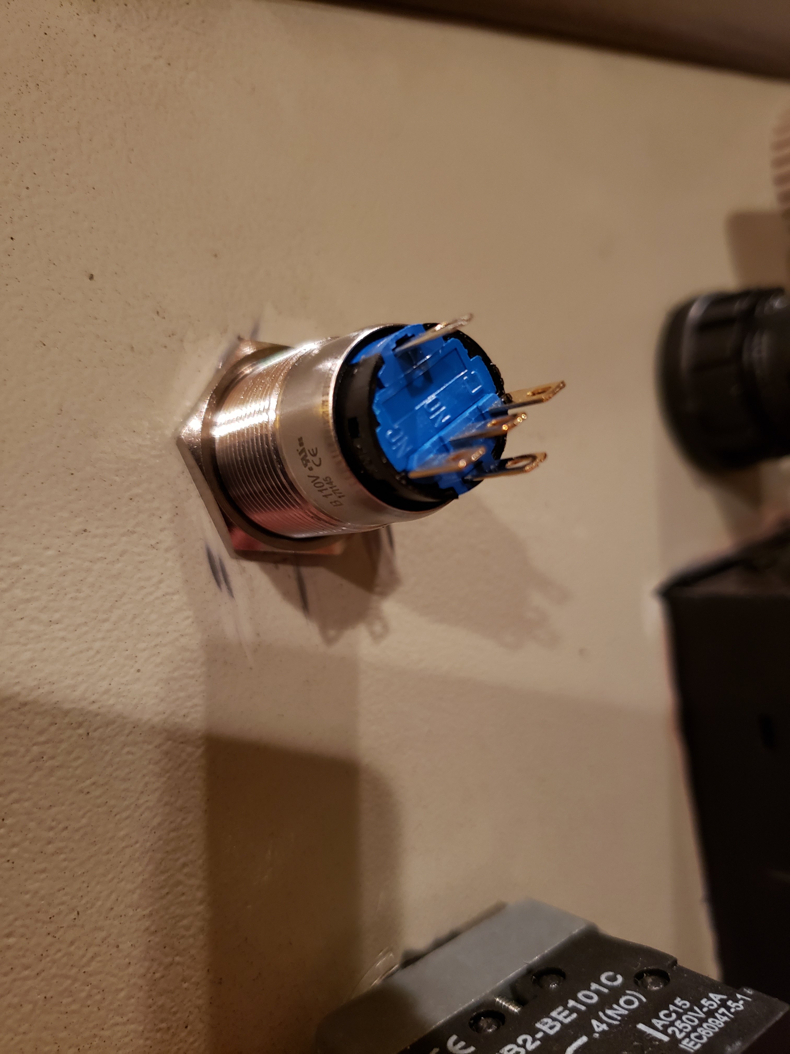
So I've decided to pull another wire from panel to the spa GFCI so illI'have 4 coming into spa panel. After lookinge charts, it looks like I could get away with running 12g cord from my controllers 6 feet to my 5500 watts heaters in my boil and HLT. Is that what most do? I am a bit confused on how this alarm switch/ pump switches are wired up, there is a +,-,NO,NC,and a C marked.
Attachments
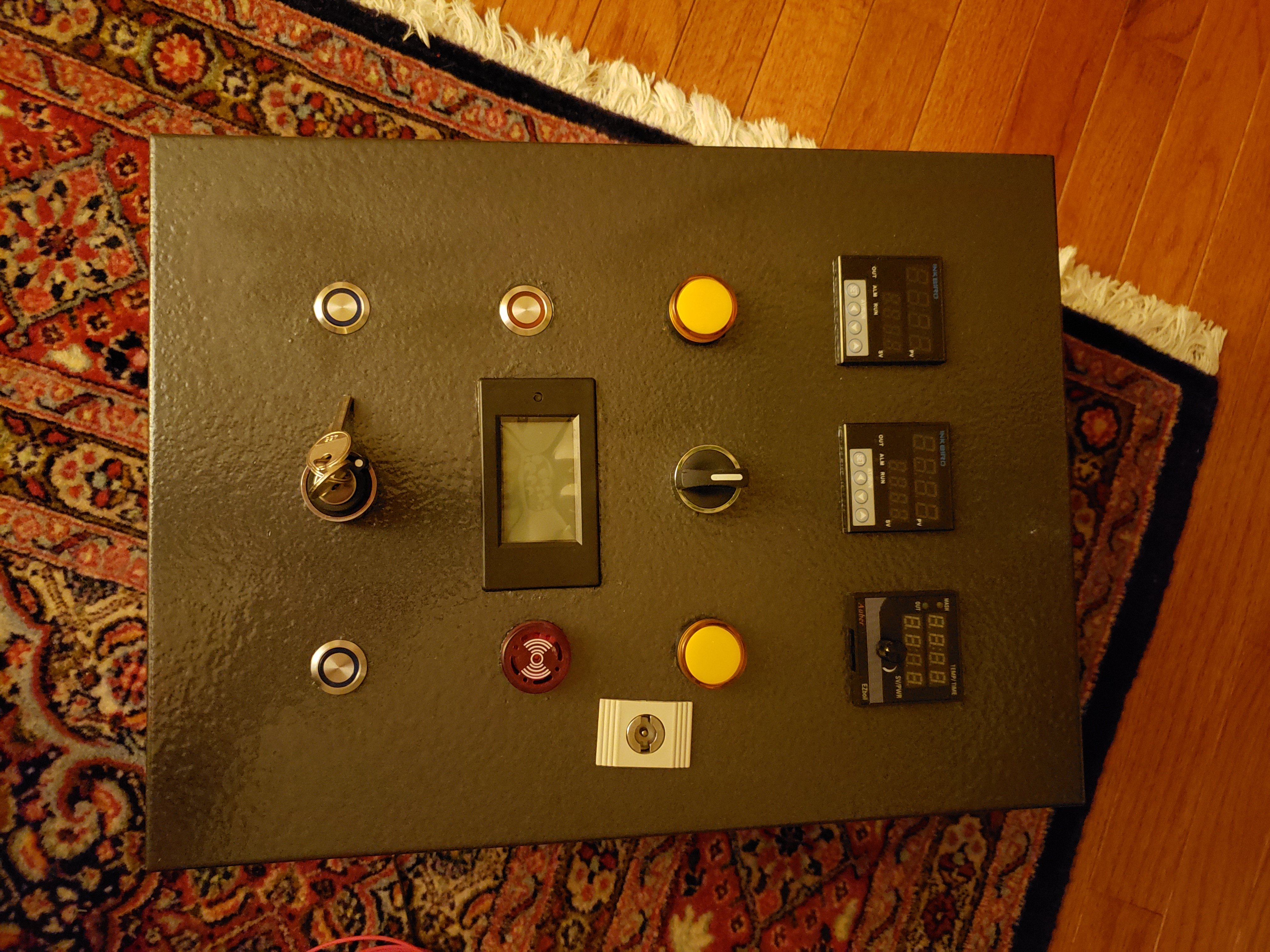
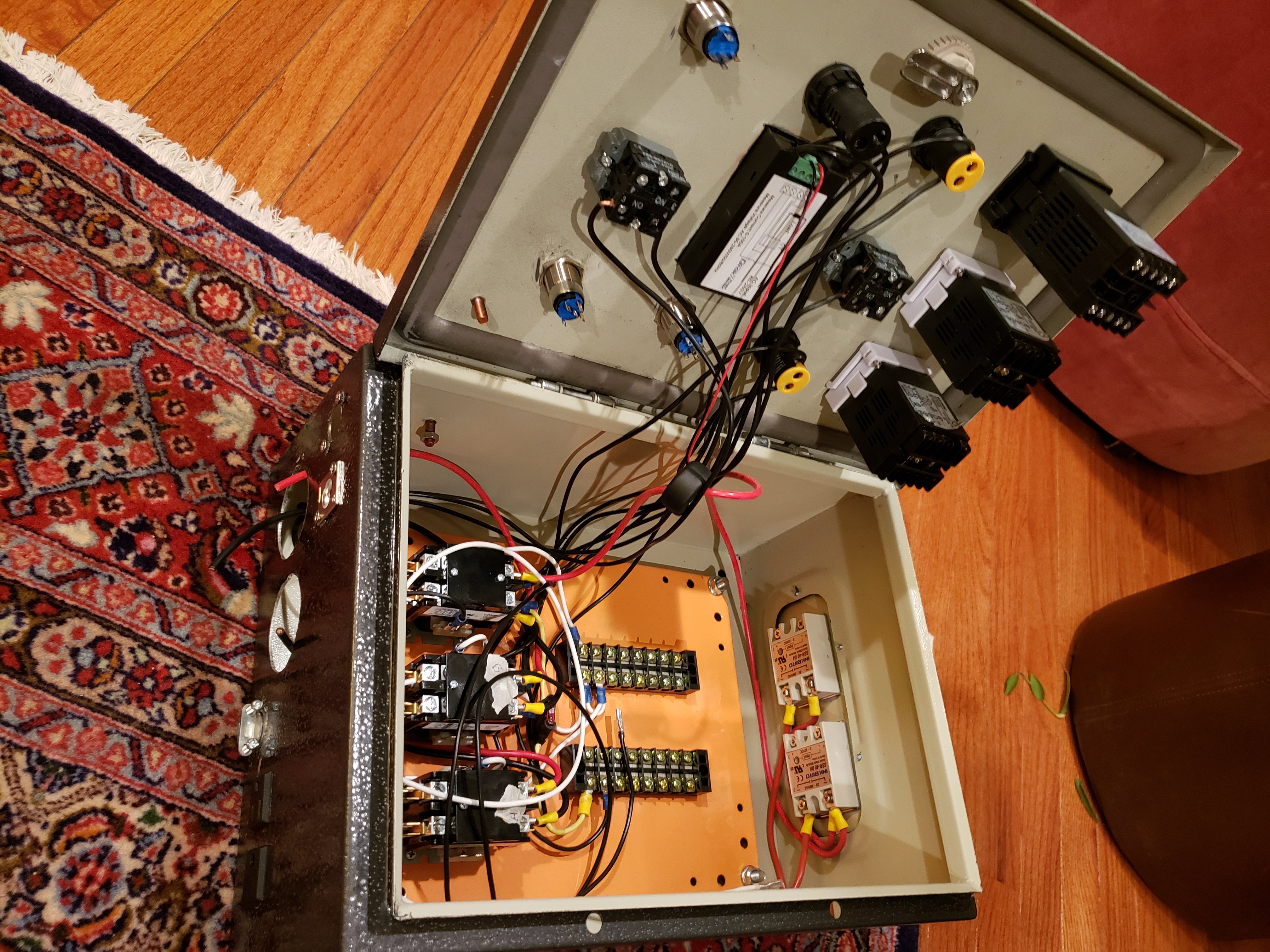
If you wanted to run 12AWG wire to your element, to be kosher you should put 25A fuses where the wire size reduces from 10AWG to 12AWG. I believe most people are using 10AWG cord to feed their 5500W elements. What type of cord are you planning to run to your element?So I've decided to pull another wire from panel to the spa GFCI so illI'have 4 coming into spa panel. After lookinge charts, it looks like I could get away with running 12g cord from my controllers 6 feet to my 5500 watts heaters in my boil and HLT. Is that what most do? I am a bit confused on how this alarm switch/ pump switches are wired up, there is a +,-,NO,NC,and a C marked.
The NO, NC, and C terminals are the power terminals. C is common between the other two. For normal operation, the incoming hot wire is connected to the C terminal, and the load side wire connected to the NO (normally open) terminal. The + and - terminals are for the LED lamps in the switches. The fact that they are labeled + & - implies that the LED's are DC rather than AC, which would require a separate power supply to use them. What are the actual switch part numbers?
Edit: The Auber switches that look like the ones on your panel have 120V AC LED's, but the LED terminals are labeled + & - . Here's how they are typically wired (from the Auber site.)

Brew on
Last edited:
I'm partial to the all SS Tri-clamp with integrated L6-30 plug elements. Easy to remove for cleaning, and the integrated plug makes for a much cleaner installation than the various cover option used with screw terminal elements. PM @augiedoggy , he can tell you where to buy them cheap.Thanks Doug, I think I will run 10/2 wire to the elements, 2 hots and a ground. I have not bought the elements yet, can you suggest cost effective 5500 watt elements?
Brew on
Similar threads
- Replies
- 20
- Views
- 1K
- Replies
- 37
- Views
- 3K
- Replies
- 11
- Views
- 868

Latest posts
-

-

-
The Dysfunctional-Palooza Obnoxious Masshole BS Thread
- Latest: TheDudeLebowski
-

-

-
-
