• Please visit and share your knowledge at our sister communities:
  • If you have not, please join our official Homebrewing Facebook Group!

    Homebrewing Facebook Group

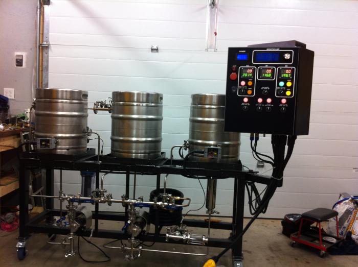
Single Tier eHERMS TriClamp (mostly) build

Homebrew Talk

Help Support Homebrew Talk:

This site may earn a commission from merchant affiliate links, including eBay, Amazon, and others.
Going to have to be custom coded. I have 3 relays that interlock the elements (so it is impossible to engage more then 2 elements), these relays will be fed from the BT (i'm probably going to hardwire them to the element off switch so that i have that hardware disconnect). For now "AUTO" will probably just be HLT AND BK.

Due to this setup all of this will have to be custom coded, I've got a decent idea how i'm going to tackle most of it (for now I just want element control BK/DUAL/HLT though). Once i get my control panel cut and wiring i'm going to look at modifying the code to make it work. I'll let you know once I get there.

I was guessing as much. Although now that I stop to think about it with relays to do the switching...I wonder if you could just set up the relay on one of the valve outputs, and then set it up under valve profiles...
I'll have to think on that.
 
You could and I thought about this. Problem is my switches are tied to a RGBIO8 and acting as a "soft-switch", and the BT doesn't support controlling 3 outputs based off the position of the one switch. So I would of had to use switches to control each relay if i wanted to be able to manually control it.

Also the valve profiles don't really line up ideally for this (although BT V3.0 sounds like it will improve upon this).
 
If you don't already have, put a ball valve in between the kettle and filter so if it clogs you could just close it and take it apart. I can't see if you have a valve already so sorry if its obvious advice lol
 
If you don't already have, put a ball valve in between the kettle and filter so if it clogs you could just close it and take it apart. I can't see if you have a valve already so sorry if its obvious advice lol

haha, no worries. All advice is still appreciated.

Yea, all keggles have TC butterfly valves on the bottom drain, much nicer then the TC ball valves IMHO if I did it all over I'd probably spring for more butterfly valves.
 
Not too much progress to post. Working on getting my control panel labeling done then I'll be able to finish the wiring/testing.

Odds and ends with the brewery (finishing welds, removing rust, priming, etc). Thought I'd post this pic of our other over elaborate project. It's going to be a 3 chamber glycol chiller fermentation/conditioning chamber. Below is a pick of the frankenchiller DIY glycol chiller. Coil will be submersed in container of glycol and then pumped through transmission coolers in each chambers.

I'll likely start a separate thread on it once I have more to post.

IMG_0930.jpg
 
Finally got my control panel cover labeled/assembled. Now on to the wiring....

The labeling was engraved, its just like the little tags everyone uses, but instead its one control panel sized piece. Had I known I was going to go this way I would have changed the design a bit. Light shines through the engraved (white) parts really well, would be perfect to have back lighting. I probably would have ditched the indicator LED's and instead backlit the text according to the state of the switches.

DSC01673.jpg


DSC01674.jpg
 
Very nice! Can you tell us more about the engraved CP overlay you have? Where did you have it done and about how much it cost? I like the look and would like to do something similar. Great job.
 
Very nice! Can you tell us more about the engraved CP overlay you have? Where did you have it done and about how much it cost? I like the look and would like to do something similar. Great job.

I had it done locally by someone I know, I only had to pay for the material which wasn't crazy as I recall ($20-30 mayb?). I just gave him the design in CAD. Almost all sign/engraving places have one of these machines, assuming your panel isn't huge it shouldn't be hard to find someone to do it.

It's 1/16" thick black/white stock material, I secured it to the panel with double sided tape (the buttons/switches hold most of it down).
 
Updated pic with most of the wiring done, bit more to do. Went a bit crazy with the wiring, but with this many wires I felt I had to keep it tidy.
Messing with the Brewtroller code now to get the element select switch to work as I want.

IMG_0968.jpg
 
Nothing wrong with being neat with your wiring! You'll be better off in the long run! That's a real nice job!
 
I'm still dying to find out how the trub filter works in the bottom drain suspended like that. Any updates or testing?
 
Painting the stand, getting the control panel mounted and trying to work out the last few bugs/wiring. Going to try and get the hard plumbing done soon. Nothing with testing the filter, my guess would be probably a few weeks away from that point yet. I will post back with how it goes.
 
So I thought I'd post a few more pics of the little bit of progress.
Control panel is almost fully wired, just a little bit more testing/tweaking to do. Stand is painted and hoping to get the hard plumbing done soon.

IMG_0987.jpg


DSC01688.jpg


DSC01690.jpg


DSC01691.jpg
 
Coming along nicely! That's really a nice job on the control panel! I always like to see a neat wiring job!
 
A small update. Got most of the plumbing done, may re-do one based on the slopes as I have extra piping. Have to wait and see. Just have to finish up some odds and ends and do the water plumbing and element wiring next.

IMG_0994.jpg
 
Another small update. Got a few more things, finally heating water. The 10kW gives it some serious speed.

Almost there (thank god).

IMG_1002.jpg
 
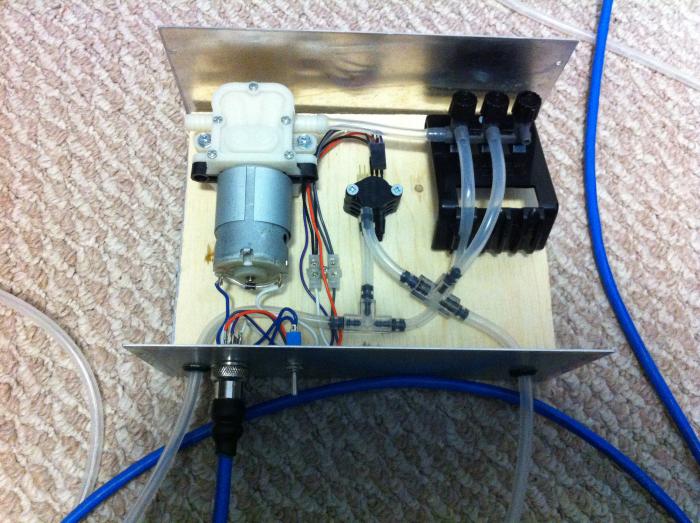
Got the "bubbler box" setup for the BrewTroller volume measurements. Keggles aren't here to test with but it seems to work pretty good with a bucket of water.

Not real pretty inside but as I expect it almost never to be opened I didn't go too crazy with it. Pump is a 12V micro pump from eBay, sensors are MPX5010-DP and the rest is aquarium supply gear from a local pet shop.

Just have to finish installing some 1/4" SS dip tubes in to the keggles for this and should be good to go for volume measurement in HLT & BK.

IMG_1005.jpg
 
Not too much progress to post. Working on getting my control panel labeling done then I'll be able to finish the wiring/testing.

Odds and ends with the brewery (finishing welds, removing rust, priming, etc). Thought I'd post this pic of our other over elaborate project. It's going to be a 3 chamber glycol chiller fermentation/conditioning chamber. Below is a pick of the frankenchiller DIY glycol chiller. Coil will be submersed in container of glycol and then pumped through transmission coolers in each chambers.

I'll likely start a separate thread on it once I have more to post.

Just currious where you are with this project. Was considering doing something similar...
 
Which one?

The brewery is up and running.

The glycol is on hold. Using a chest freezer for now.
 
Very ,very early planning stages of a build ...drinking a beer and reading lol.... I love the idea of four elements :rockin:

Seems the most logical way to go to have speed or back to back brewing:mug:

Has control been an issue? This is definitely the road I'm going down bumpy as it may be... ;)

Thanks
 
I initially had some problems with the BrewTroller locking up/etc but I've got most of that resolved now. Still trying different things to figure out the best process, but its been working pretty well lately (but I've done a fair bit of tweaking/modifications).

The 4 elements is pretty excessive, but I'll tell you I'm glad I did it. I get annoyed at times waiting for 10kW to heat up, 5500W would have drove me crazy. I've been meaning to post some graphs on the ramp times with different elements.
 
Nice build, just found this searching around.
I plan to upgrade to electric soon and want to model mine somewhat after yours.
I have a few questions:
Why do you use "X" junction in the inlet of your pumps?
Do you have any issues priming your pumps?
In the spirit of saving a little money, would the assembly work fine without the 6" tri-clamp spacer tubing?
What is the advantage of having the three-way valves directly over the pumps, could these be replaced with a "T"?
Is you system designed to clean in place, if so what is the advantage of having tri-clamp fittings over camlock and threaded fittings?
How did you place the dual elements in the keggles and what is the minimum fluid level that you have to maintain to keep your elements submerged?

Hey,

Not sure I can in good conscious recommend anyone do what I do (very little of it was necessary).

I've actually done some further mods (added a 3rd pump so it's easier to do back to back batches). Each vessel now has its own pump.

To Answer your questions:

I wanted the lowest point of all the plumbing to be able to drain. Whether you do tri-clamp or threaded/etc. I would recommend trying to do this. The X is there so the MT/BK can enter the pump and the bottom clamp can be removed to drain. (I now hook a valve/drain hose up to it).

I've never had any issues priming them. They're well below the liquid level and the head orientation works well for priming.

The valve handles on the 3way valves will hit each other without the spacing. You'd have to get creative and modify the handles or something without the spacers.

The 3way valve of the pumps allow me to route liquids/flush in the most possible combinations. Depending on what you want to sacrifice you cant likely do without some.

My system is not clean in place really. To be true clean in place everything would have to be sanitary welded (among other things). Ball valves are not clean in place (they can hold liquid behind the valve). I went TriClamp because I liked them, I can take them apart, reconfigure/etc. Also they made sense with the hard plumbing I did. Really, it's just personal preference in my opinion.

I soldered 2" Triclamp ferrules and built custom triclamp element enclosures (you can now buy nice ones, I wouldn't have made them if they were available at the time). BrewHardware.com has some nice stuff for this now. One goes in the front, one in the back. I won't run them with less then ~3.5gallons, If I was more careful about mounting them I would have went less. If you get pots you could mount them much lower as well...

Any other questions let me know, I'm going to try to update the pics with the mods I've done soon.
 
Back
Top