• Please visit and share your knowledge at our sister communities:
  • If you have not, please join our official Homebrewing Facebook Group!

    Homebrewing Facebook Group

Simple Digital Brew Thermometer with Control Out

Homebrew Talk

Help Support Homebrew Talk:

This site may earn a commission from merchant affiliate links, including eBay, Amazon, and others.
If you are going to attempt this, use IAR Embedded, the sample project compiles with no problem. The CSS project from TI is a bit messed... The IAR Embedded compile is very clean and easy. I will document the steps.

I need to test and calibrate the system, but the headless unit works!! On too the Wifi unit!!

Joel
 
The headless unit based on the ez430-RF2500 is done.


Cost: $100.00

You can add 10+ sensors to the wireless network with no changes

Powered on 4 AAA batteries, Eneloops should provide us with 12+ hours before a recharge.

The TI driver simply dumps data to a com port the format is text
with sensor number, temp, voltage so easy to work with...


Onto the ATMEL version, which is the full up controller with display and control out, and with a WiFi option.

Send questions/Suggestions.

Joel
 
Can your controller have several channels to have an all-in-one controller for all your different brew needs? i.e. Fermentation chamber, Keezer, HLT, MLT, RIMS, etc... Would be NICE to have it all wrapped up in a central box.
 
Can your controller have several channels to have an all-in-one controller for all your different brew needs? i.e. Fermentation chamber, Keezer, HLT, MLT, RIMS, etc... Would be NICE to have it all wrapped up in a central box.


Should be able to support both physically connected sensors and output switches, and "virtual sensors" and "virtual switches" ones which are connected over WiFi.

The limiting factor on the physical is the number of analog inputs and outputs, and the limit on the virtual is the update rate of the system.

Fun.
 
I have selected the following for the first build.

1) ATMEL: XMEGA-A3BU XPLAINED $39.00
2) MicroChip: MRF24WB0MB/RM $29.00
3) Analog Devices: TMP35 $1.50

I will design a PCB to hold these components and make the design available, or we can do a group buy to lower the costs.

The board will support:

Up to 8 directly connected Analog Sensors
8 digital outputs, optically isolated (5 Volts) to drive solid state relays

In addition, the software will support "Virtual Sensors", and "Virtual Switches", through a simple UDP based messaging protocol.

Might as well do it right. Any other suggestions.
Joel
 
The Watch would need another build. It doesn't seem to work on the same frequency as the ez430-RF2500

Yah, the ez430-RF2500 target boards are 2.4GHz, but you can get target boards that are in the 868MHz and 915MHz frequencies that are based on a similar but slightly different chip. You can get them from Farnell, but there has to be a US supplier too...

http://uk.farnell.com/jsp/search/productdetail.jsp?sku=1642378&_requestid=132347

Then it would be a pin-for-pin swap of your current board that you showed in post #22. It's probably not high on your priority list, but I'm throwing it out there just so you know that it's still a viable option that wouldn't require a full hardware redesign.

Thanks. It would be nice to have the temps logged on the chronos-TI watches.
 
I have selected the following for the first build.

1) ATMEL: XMEGA-A3BU XPLAINED $39.00
2) MicroChip: MRF24WB0MB/RM $29.00
3) Analog Devices: TMP35 $1.50

I will design a PCB to hold these components and make the design available, or we can do a group buy to lower the costs.

The board will support:

Up to 8 directly connected Analog Sensors
8 digital outputs, optically isolated (5 Volts) to drive solid state relays

In addition, the software will support "Virtual Sensors", and "Virtual Switches", through a simple UDP based messaging protocol.

Might as well do it right. Any other suggestions.
Joel

good luck with the tmp35's. I found them to be very accurate on the breadboard but worthless soldered onto the end of a 5' cable. I got so much noise it was reading +/- 30 degrees F. I ended up buying one wire sensors and found them to work much better. Good luck.
 
good luck with the tmp35's. I found them to be very accurate on the breadboard but worthless soldered onto the end of a 5' cable. I got so much noise it was reading +/- 30 degrees F. I ended up buying one wire sensors and found them to work much better. Good luck.

The initial testing seems to show the tmp35s to be accurate. In the datasheet ADCi indicated when driving a cable that a 0.1uF cap bypass and a 750 ohm series resistor is required. I ended up using a 0.1uF and a 560 ohm series resistor, haven't had any issues with noise.

I am driving about 26 inches of cable.

Joel
 
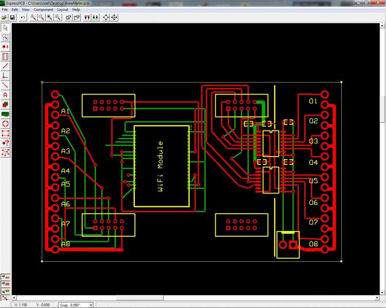
Here is a start to the interface board. ExpressPCB so it will be easy of others to spin.

Untitled.jpg
 
Latest Change

Isolated Inputs, but we can also use adapters in the DIPs to drive different temp sensors.

To Do:

Hook up the WiFi Module


rvloab.png
 
The MAX6603 gives us the RTD to voltage conversion we need with isolation, and will fit nicely on a 16 pin DIP sized board, so it can replace a TI ISO122JPE4.

I think we have the following.

1) 8 isolated inputs supporting PWM and Analog temp sensors and RTD sensors [with a small adapter board that plugs in the DIP instead of the ISO122 to support the use of RTDs]
2) 8 isolated outputs to drive Solid State Relays.
3) WiFi connections to virtual and remote sensors and switches


I will update the board tomorrow, and hope to spin it sometime next week.

Joel
 
1) Put in the ground plane on the isolated output side
2) Corrected the voltage on the Input Isolation side of the board
3) Putting the BOM on the board.

TBD: Bypass caps on the input isolation side of the board. Digital Ground plane, signal and power labels

Joel

156v29e.png
 
Sigh, one last board addition, it adds some cost, but if you don't want to isolate the inputs you could populate only 1/2 of them.

I am using murata isolated DC to DC converters to provide the input and output power and the power for the XMEGA.
http://www.murata-ps...ncl/kdc_ntv.pdf

The board will take in 12VDC.

Joel
 
Need to hook up the power to the XMEGA, and size the included 3.3 V regulator to make sure it can drive the WiFi module. Then I will spin a few boards for testing.

a0jxoj.png
 
I need to up the 5VDC for the board, but the 5VDC for the switching will remain the same.

To do the hot swap for USB....

Linear LTC4412 - Low Loss PowerPath Controller in ThinSOT will be used to switch between the Board power and the USB power

Getting close.

Joel
 
why are you designing your own circuit instead of going the aurduino or netduino route? Seems like a lot of work when there are already boards out there...
 
why are you designing your own circuit instead of going the aurduino or netduino route? Seems like a lot of work when there are already boards out there...

I am only designing the base board to support the xmega-a3bu xplained board. We need to make sure that we don't fry the processor if something bad happens to the sensors or activators.

The netduino is an option, but I would still design a base board for it to isolate the analog inputs and outputs.

It was a toss up, but the XMEGA-A3BU XPLAINED as a display on the board so I went with it. http://store.atmel.com/PartDetail.aspx?q=p:10500293

Another great option was the NXP Mbed.

Lot of work, or fun.

Joel
 
rosienej Powered on 4 AAA batteries said:
Clever thread!

Just my two cents: here is what I did with my brewtroller board, powered by 12V solar panel.
Doing this for a lower voltage will be cheaper and easier...

Photo%20Jan%2004%2C%206%2058%2036%20PM.jpg
 
Clever thread!

Just my two cents: here is what I did with my brewtroller board, powered by 12V solar panel.
Doing this for a lower voltage will be cheaper and easier...

Photo%20Jan%2004%2C%206%2058%2036%20PM.jpg

The brewtroller is a nice product. Here is my rough, small quantity price estimate...

1) XMEGA $40.00 (with the display,bootloader, USB interface etc..)
2) Wifi $30.00
3) The board spin ($30.00 small quant)
4) Electronics for 1 temp probe but up to 8 SSR $50.00 (each additional probe is around $20.00, if isolated analog, <$10 isolated digital or RTD)
5) Additional parts (case etc) $50.00

ROM $200.00

A group buy on the board and parts might get the full up cost to $150.00

It is fun to do the custom work. I will put up all the design files once I test the board.
Joel
 
Sometimes simpler is better.

I am going to use a simple USB type A connector to provide 5Volts to the XMEGA. I might put on a type B USB connector and enable a hot swap.

How important is this? I am assuming the USB will be used only for software updates in the finished design.


Joel
 
Simpler might be better.

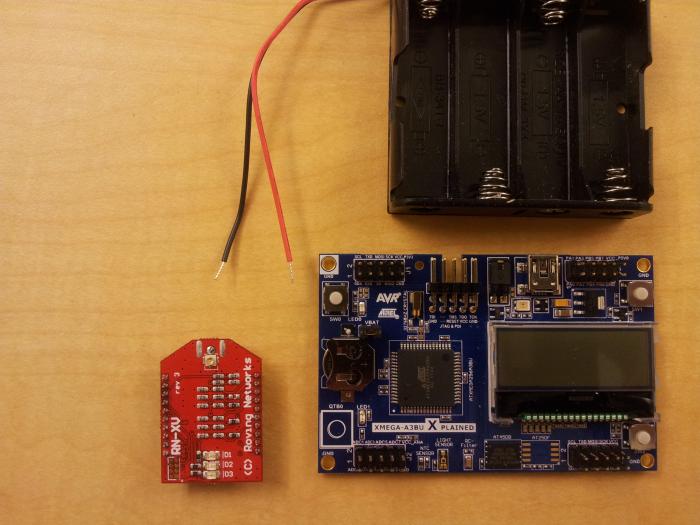
I am going to glue the following parts together and be done with the design. Want to get my conical copper/settling tank done after this one.

Components and planned unit for case sizing.

Next step
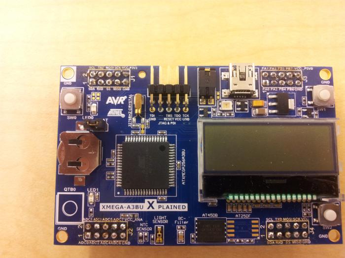
1) flip the connecters on the xmega-A3BU xplained
2) mount parts on prototyping board.

Joel

20121014_115814.jpg


20121014_120005.jpg
 
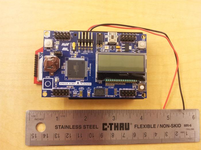
Flipped the connectors....

Think is am going to mount it on a board and wirewrap the unit to the WiFly unit.... might provide 5 volt regulator on board for other devices.

Plans:
1) will use analog devices temp sensors, TMP03 initially, but the board will support RTDs without a problem.
2) The unit will take a UDP packet with configuration data (update rate, signal polarity, temp sensor temp etc)
3) The unit will report temps by sending UDP packets.
4) The unit will take UDP packets that has a list of temps and times and generate a relay signal.

I will write a little android app....

Joel

20121015_125333.jpg
 
Back
Top