// ======================================================= Includes =======================================================
#include <util/delay.h> // Using _delay_ms(#) rather than delay(#) saves 146 bytes of sketch size!
// ================================================== User-Specific Data ==================================================
#define Sensor1 "Carboy_1_Temperature" // Enter whatever you wish to call your first sensor inside the double quotes
#define Sensor2 "Ambient_Temperature" // Enter whatever you wish to call your second sensor inside the double quotes
#define FEEDID "102607" // Enter the feed ID assigned to you by Cosm.com inside the double quotes
#define APIKEY "xxxxxxxxD0kjGte5FxxxxxxxxxCSAKxva3hwZ3hCxxxxxxxx" // Enter the feed APIKEY assigned to you by Cosm.com inside the double quotes
#define USERAGENT "Test" // Enter
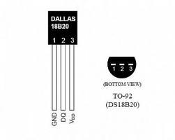
const uint8_t pin = 3; // The pin that the data pin of the DS18B20s is connected to
const uint8_t Sensor[2][8] = {{ 0x28, 0xE0, 0xF7, 0x83, 0x04, 0x00, 0x00, 0x0F }, // Thermowell sensor
{ 0x28, 0x68, 0xEF, 0x7D, 0x04, 0x00, 0x00, 0x62 }}; // Ambient room air sensor
#define DELAY 5000 // The delay in milliseconds between sensor readings; the code below takes around a second to run total
// ===================================================== Definitions ======================================================
#define PIN_TO_BASEREG(pin) (portInputRegister(digitalPinToPort(pin)))
#define PIN_TO_BITMASK(pin) (digitalPinToBitMask(pin))
#define IO_REG_TYPE uint8_t
#define IO_REG_ASM asm("r30")
#define DIRECT_READ(base, mask) (((*(base)) & (mask)) ? 1 : 0)
#define DIRECT_MODE_INPUT(base, mask) ((*(base+1)) &= ~(mask))
#define DIRECT_MODE_OUTPUT(base, mask) ((*(base+1)) |= (mask))
#define DIRECT_WRITE_LOW(base, mask) ((*(base+2)) &= ~(mask))
#define DIRECT_WRITE_HIGH(base, mask) ((*(base+2)) |= (mask))
#define STARTCONVO 0x44 // Tells device to take a temperature reading and put it on the scratchpad
#define READSCRATCH 0xBE // Read EEPROM
#define TEMP_LSB 0
#define TEMP_MSB 1
#define DEBUG 0 // Controls the inclusion or exclusion of serial debug information; 0 for no serial output 1 for serial output
// AVRJazz Mega328 SPI I/O
#define SPI_PORT PORTB
#define SPI_DDR DDRB
#define SPI_CS PORTB2
// Wiznet W5100 Op Code
#define WIZNET_WRITE_OPCODE 0xF0
#define WIZNET_READ_OPCODE 0x0F
// Wiznet W5100 Register Addresses
#define MR 0x0000 // Mode Register
#define GAR 0x0001 // Gateway Address: 0x0001 to 0x0004
#define SUBR 0x0005 // Subnet mask Address: 0x0005 to 0x0008
#define SAR 0x0009 // Source Hardware Address (MAC): 0x0009 to 0x000E
#define SIPR 0x000F // Source IP Address: 0x000F to 0x0012
#define RMSR 0x001A // RX Memory Size Register
#define TMSR 0x001B // TX Memory Size Register
#define S0_MR 0x0400 // Socket 0: Mode Register Address
#define S0_CR 0x0401 // Socket 0: Command Register Address
#define S0_IR 0x0402 // Socket 0: Interrupt Register Address
#define S0_SR 0x0403 // Socket 0: Status Register Address
#define S0_DIPR 0x040C // Socket 0: Destination IP Address: 0x040C to 0x040F
#define S0_DPORT 0x0410 // Socket 0: Destination Port: 0x0410 to 0x0411
#define S0_PORT 0x0404 // Socket 0: Source Port: 0x0404 to 0x0405
#define SO_TX_FSR 0x0420 // Socket 0: Tx Free Size Register: 0x0420 to 0x0421
#define S0_TX_RD 0x0422 // Socket 0: Tx Read Pointer Register: 0x0422 to 0x0423
#define S0_TX_WR 0x0424 // Socket 0: Tx Write Pointer Register: 0x0424 to 0x0425
#define S0_RX_RSR 0x0426 // Socket 0: Rx Received Size Pointer Register: 0x0425 to 0x0427
#define S0_RX_RD 0x0428 // Socket 0: Rx Read Pointer: 0x0428 to 0x0429
#define TXBUFADDR 0x4000 // W5100 Send Buffer Base Address
#define RXBUFADDR 0x6000 // W5100 Read Buffer Base Address
// S0_MR values
#define MR_CLOSE 0x00 // Unused socket
#define MR_TCP 0x01 // TCP
#define MR_UDP 0x02 // UDP
#define MR_IPRAW 0x03 // IP LAYER RAW SOCK
#define MR_MACRAW 0x04 // MAC LAYER RAW SOCK
#define MR_PPPOE 0x05 // PPPoE
#define MR_ND 0x20 // No Delayed Ack(TCP) flag
#define MR_MULTI 0x80 // support multicating
// S0_CR values
#define CR_OPEN 0x01 // Initialize or open socket
#define CR_LISTEN 0x02 // Wait connection request in tcp mode(Server mode)
#define CR_CONNECT 0x04 // Send connection request in tcp mode(Client mode)
#define CR_DISCON 0x08 // Send closing reqeuset in tcp mode
#define CR_CLOSE 0x10 // Close socket
#define CR_SEND 0x20 // Update Tx memory pointer and send data
#define CR_SEND_MAC 0x21 // Send data with MAC address, so without ARP process
#define CR_SEND_KEEP 0x22 // Send keep alive message
#define CR_RECV 0x40 // Update Rx memory buffer pointer and receive data
// S0_SR values
#define SOCK_CLOSED 0x00 // Closed
#define SOCK_INIT 0x13 // Init state
#define SOCK_LISTEN 0x14 // Listen state
#define SOCK_SYNSENT 0x15 // Connection state
#define SOCK_SYNRECV 0x16 // Connection state
#define SOCK_ESTABLISHED 0x17 // Success to connect
#define SOCK_FIN_WAIT 0x18 // Closing state
#define SOCK_CLOSING 0x1A // Closing state
#define SOCK_TIME_WAIT 0x1B // Closing state
#define SOCK_CLOSE_WAIT 0x1C // Closing state
#define SOCK_LAST_ACK 0x1D // Closing state
#define SOCK_UDP 0x22 // UDP socket
#define SOCK_IPRAW 0x32 // IP raw mode socket
#define SOCK_MACRAW 0x42 // MAC raw mode socket
#define SOCK_PPPOE 0x5F // PPPOE socket
#define TX_BUF_MASK 0x07FF // Tx 2K Buffer Mask:
#define RX_BUF_MASK 0x07FF // Rx 2K Buffer Mask:
#define NET_MEMALLOC 0x05 // Use 2K of Tx/Rx Buffer
#define TCP_PORT 80 // TCP/IP Port
#define MAX_BUF 210
// ============================================== Project scoped variables ================================================
IO_REG_TYPE bitmask;
volatile IO_REG_TYPE *baseReg;
uint8_t scratchPad[2];
uint8_t buf[MAX_BUF]; // The character buffer in which the HTTP Put will be constructed
// ========================================================================================================================
void SPI_Write(uint16_t addr,uint8_t data) {
SPI_PORT &= ~(1<<SPI_CS); // Activate the CS pin
SPDR = WIZNET_WRITE_OPCODE; // Start Wiznet W5100 Write OpCode transmission
while(!(SPSR & (1<<SPIF))); // Wait for transmission complete
SPDR = (addr & 0xFF00) >> 8; // Start Wiznet W5100 Address High Bytes transmission
while(!(SPSR & (1<<SPIF))); // Wait for transmission complete
SPDR = addr & 0x00FF; // Start Wiznet W5100 Address Low Bytes transmission
while(!(SPSR & (1<<SPIF))); // Wait for transmission complete
SPDR = data; // Start Data transmission
while(!(SPSR & (1<<SPIF))); // Wait for transmission complete
SPI_PORT |= (1<<SPI_CS); // CS pin is not active
}
unsigned char SPI_Read(uint16_t addr) {
SPI_PORT &= ~(1<<SPI_CS); // Activate the CS pin
SPDR = WIZNET_READ_OPCODE; // Start Wiznet W5100 Read OpCode transmission
while(!(SPSR & (1<<SPIF))); // Wait for transmission complete
SPDR = (addr & 0xFF00) >> 8; // Start Wiznet W5100 Address High Bytes transmission
while(!(SPSR & (1<<SPIF))); // Wait for transmission complete
SPDR = addr & 0x00FF; // Start Wiznet W5100 Address Low Bytes transmission
while(!(SPSR & (1<<SPIF))); // Wait for transmission complete
SPDR = 0x00; // Send Dummy transmission for reading the data
while(!(SPSR & (1<<SPIF))); // Wait for transmission complete
SPI_PORT |= (1<<SPI_CS); // CS pin is not active
return(SPDR);
}
void W5100_Init(void)
{
// Ethernet Setup
const unsigned char mac_addr[] = {0x00, 0x1D, 0x0D, 0x2C, 0x55, 0x3D};
const unsigned char ip_addr[] = {192,168,11,8};
const unsigned char sub_mask[] = {255,255,255,0};
const unsigned char gtw_addr[] = {192,168,11,1};
const unsigned char cosm_addr[] = {216,52,233,121};
// Setting the Wiznet W5100 Mode Register: 0x0000
SPI_Write(MR,0x80); // MR = 0b10000000;
// Setting the Wiznet W5100 Gateway Address (GAR): 0x0001 to 0x0004
SPI_Write(GAR + 0,gtw_addr[0]);
SPI_Write(GAR + 1,gtw_addr[1]);
SPI_Write(GAR + 2,gtw_addr[2]);
SPI_Write(GAR + 3,gtw_addr[3]);
// Setting the Wiznet W5100 Source Address Register (SAR): 0x0009 to 0x000E
SPI_Write(SAR + 0,mac_addr[0]);
SPI_Write(SAR + 1,mac_addr[1]);
SPI_Write(SAR + 2,mac_addr[2]);
SPI_Write(SAR + 3,mac_addr[3]);
SPI_Write(SAR + 4,mac_addr[4]);
SPI_Write(SAR + 5,mac_addr[5]);
// Setting the Wiznet W5100 Sub Mask Address (SUBR): 0x0005 to 0x0008
SPI_Write(SUBR + 0,sub_mask[0]);
SPI_Write(SUBR + 1,sub_mask[1]);
SPI_Write(SUBR + 2,sub_mask[2]);
SPI_Write(SUBR + 3,sub_mask[3]);
// Setting the Wiznet W5100 IP Address (SIPR): 0x000F to 0x0012
SPI_Write(SIPR + 0,ip_addr[0]);
SPI_Write(SIPR + 1,ip_addr[1]);
SPI_Write(SIPR + 2,ip_addr[2]);
SPI_Write(SIPR + 3,ip_addr[3]);
// Setting the Wiznet W5100 RX and TX Memory Size (2KB),
SPI_Write(RMSR,NET_MEMALLOC);
SPI_Write(TMSR,NET_MEMALLOC);
// Setting the Wiznet to connect to the Cosm server port 80
SPI_Write(S0_DIPR + 0,cosm_addr[0]);
SPI_Write(S0_DIPR + 1,cosm_addr[1]);
SPI_Write(S0_DIPR + 2,cosm_addr[2]);
SPI_Write(S0_DIPR + 3,cosm_addr[3]);
SPI_Write(S0_DPORT,((TCP_PORT & 0xFF00) >> 8 ));
SPI_Write(S0_DPORT + 1,(TCP_PORT & 0x00FF));
SPI_Write(S0_PORT,((1 & 0xFF00) >> 8 )); // Set the source port to 1
SPI_Write(S0_PORT + 1,(1 & 0x00FF)); // Set the source port to 1
// Set the Wiznet to use TCP
SPI_Write(S0_MR,MR_TCP); // Set the mode to TCP
}
void UploadDataPoint(void) {
// Connect to the Cosm server and upload the data
SPI_Write(S0_CR,CR_OPEN);
while(SPI_Read(S0_CR));
do {
_delay_ms(1);
} while(SPI_Read(S0_SR)!=SOCK_INIT);
close(0);
SPI_Write(S0_MR,MR_TCP);
SPI_Write(S0_CR,CR_CONNECT); // Open Socket
// Wait for Opening Process
while(SPI_Read(S0_CR));
do {
_delay_ms(1);
} while(SPI_Read(S0_SR)!=SOCK_ESTABLISHED);
send(0,buf,strlen((char *)buf));
}
void close(uint8_t sock)
{
if (sock != 0) return;
// Send Close Command
SPI_Write(S0_CR,CR_CLOSE);
// Waiting until the S0_CR is clear
while(SPI_Read(S0_CR));
}
void disconnect(uint8_t sock)
{
if (sock != 0) return;
// Send Disconnect Command
SPI_Write(S0_CR,CR_DISCON);
// Wait for Disconecting Process
while(SPI_Read(S0_CR));
}
uint16_t send(uint8_t sock,const uint8_t *buf,uint16_t buflen)
{
uint16_t ptr,offaddr,realaddr,txsize,timeout;
if (buflen <= 0 || sock != 0) return 0;
// Make sure the TX Free Size Register is available
txsize=SPI_Read(SO_TX_FSR);
txsize=(((txsize & 0x00FF) << 8 ) + SPI_Read(SO_TX_FSR + 1));
timeout=0;
while (txsize < buflen) {
_delay_ms(1);
txsize=SPI_Read(SO_TX_FSR);
txsize=(((txsize & 0x00FF) << 8 ) + SPI_Read(SO_TX_FSR + 1));
// Timeout for approx 1000 ms
if (timeout++ > 1000) {
// Disconnect the connection
disconnect(sock);
return 0;
}
}
// Read the Tx Write Pointer
ptr = SPI_Read(S0_TX_WR);
offaddr = (((ptr & 0x00FF) << 8 ) + SPI_Read(S0_TX_WR + 1));
while(buflen) {
buflen--;
// Calculate the real W5100 physical Tx Buffer Address
realaddr = TXBUFADDR + (offaddr & TX_BUF_MASK);
// Copy the application data to the W5100 Tx Buffer
SPI_Write(realaddr,*buf);
offaddr++;
buf++;
}
// Increase the S0_TX_WR value, so it point to the next transmit
SPI_Write(S0_TX_WR,(offaddr & 0xFF00) >> 8 );
SPI_Write(S0_TX_WR + 1,(offaddr & 0x00FF));
// Now Send the SEND command
SPI_Write(S0_CR,CR_SEND);
// Wait for Sending Process
while(SPI_Read(S0_CR));
return 1;
}
uint8_t read_bit(void) {
IO_REG_TYPE mask=bitmask;
volatile IO_REG_TYPE *reg IO_REG_ASM = baseReg;
uint8_t r;
noInterrupts();
DIRECT_MODE_OUTPUT(reg, mask);
DIRECT_WRITE_LOW(reg, mask);
_delay_us(3);
DIRECT_MODE_INPUT(reg, mask); // let pin float, pull up will raise
_delay_us(10);
r = DIRECT_READ(reg, mask);
interrupts();
_delay_us(53);
return r;
}
uint8_t read() {
uint8_t bitMask;
uint8_t r = 0;
for (bitMask = 0x01; bitMask; bitMask <<= 1) {
if ( read_bit()) r |= bitMask;
}
return r;
}
void write_bit(uint8_t v) {
IO_REG_TYPE mask=bitmask;
volatile IO_REG_TYPE *reg IO_REG_ASM = baseReg;
if (v & 1) {
noInterrupts();
DIRECT_WRITE_LOW(reg, mask);
DIRECT_MODE_OUTPUT(reg, mask); // drive output low
_delay_us(10);
DIRECT_WRITE_HIGH(reg, mask); // drive output high
interrupts();
_delay_us(55);
}
else {
noInterrupts();
DIRECT_WRITE_LOW(reg, mask);
DIRECT_MODE_OUTPUT(reg, mask); // drive output low
_delay_us(65);
DIRECT_WRITE_HIGH(reg, mask); // drive output high
interrupts();
_delay_us(5);
}
}
void write(uint8_t v) {
uint8_t bitMask;
for (bitMask = 0x01; bitMask; bitMask <<= 1) write_bit( (bitMask & v)?1:0);
noInterrupts();
DIRECT_MODE_INPUT(baseReg, bitmask);
DIRECT_WRITE_LOW(baseReg, bitmask);
interrupts();
}
uint8_t reset(void) {
IO_REG_TYPE mask = bitmask;
volatile IO_REG_TYPE *reg IO_REG_ASM = baseReg;
uint8_t r;
uint8_t retries = 125;
noInterrupts();
DIRECT_MODE_INPUT(reg, mask);
interrupts();
// wait until the wire is high... just in case
do {
if (--retries == 0) return 0;
_delay_us(2);
} while ( !DIRECT_READ(reg, mask));
noInterrupts();
DIRECT_WRITE_LOW(reg, mask);
DIRECT_MODE_OUTPUT(reg, mask); // drive output low
interrupts();
_delay_us(500);
noInterrupts();
DIRECT_MODE_INPUT(reg, mask); // allow it to float
_delay_us(80);
r = !DIRECT_READ(reg, mask);
interrupts();
_delay_us(420);
return r;
}
int16_t ReadSensor(const uint8_t sensorIndex) {
write(0x55); // Choose ROM
for(uint8_t i = 0; i < 8; i++) write(Sensor[sensorIndex][i]);
write(READSCRATCH);
scratchPad[TEMP_LSB] = read();
scratchPad[TEMP_MSB] = read();
reset();
return (((int16_t)scratchPad[TEMP_MSB]) << 8) | scratchPad[TEMP_LSB];
}
// Converts the raw temperature from a DS18B20 directly to a string containing the temperature in °F
// avoids unnecessary floating point math, float variables, and casts
// TODO: May not work properly with temperatures below 32°F
void RawTempToString(uint16_t raw, char * buffer) {
uint32_t intTemp;
uint8_t numChars;
intTemp=raw*1125ul+320000ul; // Hold the temperature
if(raw<605 && raw>=0) { // We're looking at a positive number with two digits
numChars = 7;
}
else if (raw>=605) {
numChars = 8;
}
// Write the null termination, the first four digits, and then the decimal point
buffer[numChars--]='\0';
buffer[numChars--]=intTemp%10 + '0';
intTemp/=10;
buffer[numChars--]=intTemp%10 + '0';
intTemp/=10;
buffer[numChars--]=intTemp%10 + '0';
intTemp/=10;
buffer[numChars--]=intTemp%10 + '0';
intTemp/=10;
buffer[numChars--]='.';
// Continue writing the left of the decimal place until we run out of intTemp
do {
buffer[numChars--]=intTemp%10 + '0';
intTemp/=10;
} while (intTemp);
}
void itoa(long inp, char * buf) {
long temp = inp;
uint8_t numChars=0;
boolean isNegative=false;
// Check to see if there is a negative sign
if(temp<0){
isNegative=true;
numChars++;
temp*=-1;
}
do {
numChars++;
temp /= 10;
} while ( temp );
// Write the negative sign if present and the terminating null character
temp=inp;
buf[numChars]=0;
if(isNegative) {
temp*=-1;
buf[0]='-';
}
int i = numChars - 1;
do {
buf[i--] = temp%10 + '0';
temp /= 10;
} while (temp);
}
void BuildPut(uint16_t T1, uint16_t T2) {
// Convert raw temperatures into strings
char Temp1[8];
char Temp2[8];
RawTempToString(T1, (char *)Temp1);
RawTempToString(T2, (char *)Temp2);
// Set up data buffer to hold the csv data
char * dataBuffer[strlen(Sensor1)+strlen(Temp1)+strlen(Sensor2)+strlen(Temp2)+4];
strcpy((char *)dataBuffer,Sensor1);
strcat_P((char *)dataBuffer,PSTR(","));
strcat((char *)dataBuffer,Temp1);
strcat_P((char *)dataBuffer,PSTR("\n"));
strcat((char *)dataBuffer,Sensor2);
strcat_P((char *)dataBuffer,PSTR(","));
strcat((char *)dataBuffer,Temp2);
strcat_P((char *)dataBuffer,PSTR("\n"));
// Convert the length of the data buffer into a string
char dataLength[2];
itoa(strlen((char *)dataBuffer)-1,(char *)dataLength);
// Construct the HTTP Put
strcpy_P((char *)buf,PSTR("PUT /v2/feeds/"));
strcat((char *)buf,FEEDID);
strcat_P((char *)buf,PSTR(".csv HTTP/1.1\nHost: api.cosm.com\n"));
strcat_P((char *)buf,PSTR("X-ApiKey: "));
strcat((char *)buf,APIKEY);
strcat_P((char *)buf,PSTR("\nUser-Agent: "));
strcat((char *)buf,USERAGENT);
strcat_P((char *)buf,PSTR("\nContent-Length: "));
strcat((char *)buf,dataLength);
strcat_P((char *)buf,PSTR("\n\n"));
strcat((char *)buf,(char *)dataBuffer);
}
int main() {
// This code will only run once, after each powerup or reset of the board
// Set pin 3 to input
//pinMode(pin, INPUT); // This takes 136 bytes of sketch size
//DDRD = DDRD | B11110100; // This does the same thing and only takes 4 bytes of sketch size
// This does the same thing since pin 3 is set to input by default
bitmask = PIN_TO_BITMASK(pin);
baseReg = PIN_TO_BASEREG(pin);
SPI_DDR = (1<<PORTB3)|(1<<PORTB5)|(1<<PORTB2); // Set MOSI (PORTB3),SCK (PORTB5) and PORTB2 (SS) as output, others as input
SPI_PORT |= (1<<SPI_CS); // CS pin is not active
SPCR = (1<<SPE)|(1<<MSTR); // Enable SPI, Master Mode 0
#if DEBUG
Serial.begin(9600);
#endif
W5100_Init();
for (;;) {
// Request a temperature reading from all Dallas sensors on the OneWire bus
reset();
write(0xCC);
write(STARTCONVO);
_delay_ms(750); // Wait 750ms to allow for a 12-bit precision temperature reading to be taken by the DS18B20(s)
reset();
// Read the temperatures previously requested
int16_t rawTemperature1 = ReadSensor(0); // Read the first sensor
int16_t rawTemperature2 = ReadSensor(1); // Read the second sensor
BuildPut(rawTemperature1, rawTemperature2);
#if DEBUG
Serial.print((char *)buf);
#endif
UploadDataPoint();
_delay_ms(DELAY);
}
}


")


![Craft A Brew - Safale BE-256 Yeast - Fermentis - Belgian Ale Dry Yeast - For Belgian & Strong Ales - Ingredients for Home Brewing - Beer Making Supplies - [3 Pack]](https://m.media-amazon.com/images/I/51bcKEwQmWL._SL500_.jpg)