Raspberry Pi Universal Controller

Homebrew Talk - Beer, Wine, Mead, & Cider Brewing Discussion Forum

Help Support Homebrew Talk - Beer, Wine, Mead, & Cider Brewing Discussion Forum:

This site may earn a commission from merchant affiliate links, including eBay, Amazon, and others.
Joined
Aug 9, 2014
Messages
7
Reaction score
0
I live in a small apartment and so never saw the giant controllers with knobs and lights very realistic (although they do look pretty damn cool). I also wanted a controller that was flexible (with home brewing / coffee roasting / and Sous Vide in mind). I wanted it to be a comfortable size for the counter top, and finally, I want it to be future proof for home brewing by supporting a 3 vessel system.

The analog to digital board I am using has the ability to read 8 inputs but I couldn't imagine needing more then 4...so I got 6 connectors.:rockin:

I have not ordered a screen (and probably wont until I have a beta version working) but cut a piece of paper for the size of screen I am planning on, just to mockup how it looks.

sticking with the idea of having this look semi-normal on a counter top. I didn't want a heat sink sticking out so I had to grind the solid state relay heat sinks a little skinner to get them to fit. I plan on adding a fan and vents to keep them cool, and realistically if I was worried I could make this a water-tight heat sink tunnel. (but I'm not sure its worth the trouble)

Finally on the back I have a 50A 240v input with a 50A gfci breaker, and mounting hardware, mounted into the controller. I also have space for 6 fuses for protecting lower gauge wire.

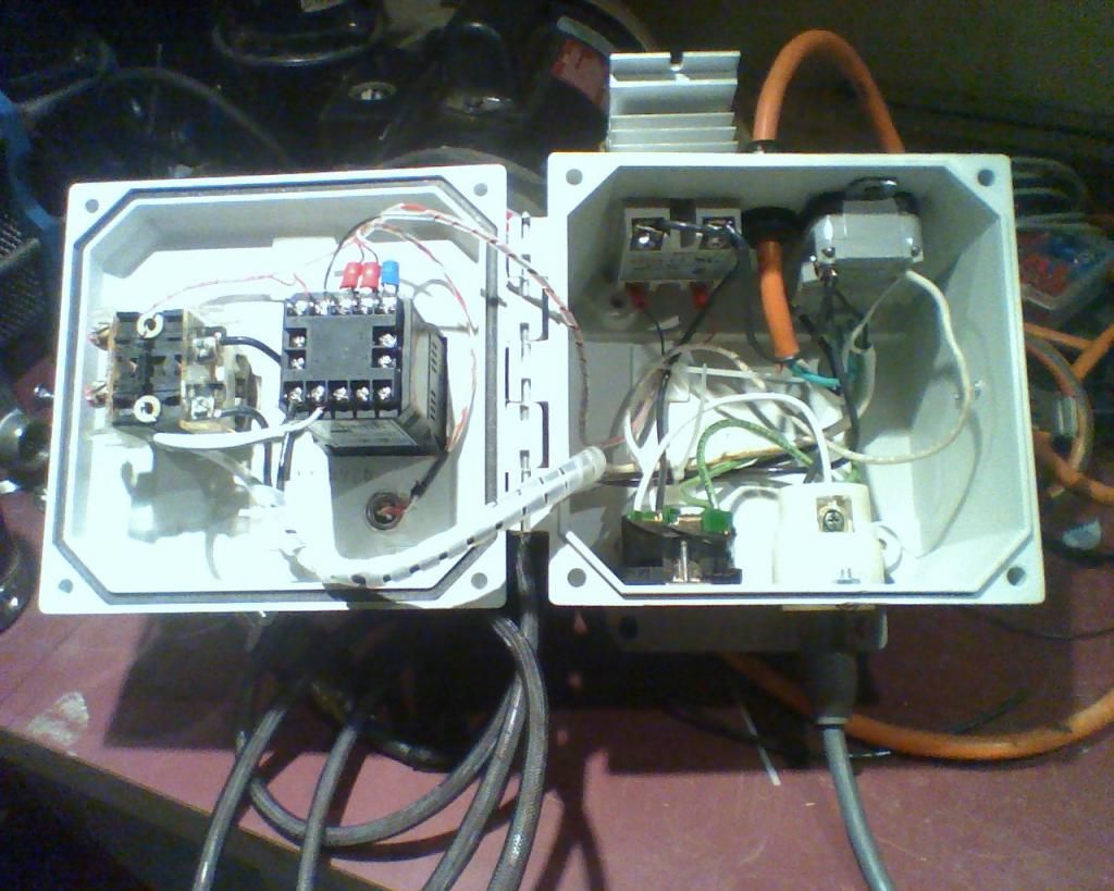
So here is what I have got so far, I don't have many tools, so all of the holes were made with a drill and dermal and look a bit rough.

So tell me what you think...:mug:

2015-03-23 20.36.17.jpg


2015-03-23 20.36.28.jpg


2015-03-23 20.40.51.jpg


2015-03-07 17.48.50.jpg


2015-03-07 17.48.59.jpg
 
I did have a few question, steaming from a lack of understanding on how 240v gfci works.

1. On most of the circuits that have a 50A input, and 30A output, they fuse both hot legs. Is this necessary with GFCI? It seems to me like if the fuse on one leg blows, there will be an imbalance and gfci will trip, cutting power to both legs.

2. can you run a 120v pump off of a 240v gfci protected circuit or will current flowing between 1 leg and neutral cause and imbalance between the two hot legs. Basically does the breaker take into account current flowing back to neutral? or just between the two hot legs?
 
i think youre going to need those heat sinks moved to be exposed to ambient air. thats a lot of heat that is going to be trapped inside the box.
 
i think youre going to need those heat sinks moved to be exposed to ambient air. thats a lot of heat that is going to be trapped inside the box.

Yeah, you definitely need to move those SSRs to heatsinks exposed to outside air. You may need a fan on top as well if you attach them all to the same heatsink.

Also, there's not nearly enough room to make reliable connections to the SSR and outlet terminals - 6 or 10 gauge wire (as required for 50A or 30A) is thick and stiff, and probably can't be bent tight enough to make those contacts.
 
i think youre going to need those heat sinks moved to be exposed to ambient air. thats a lot of heat that is going to be trapped inside the box.

Yeah, you definitely need to move those SSRs to heatsinks exposed to outside air. You may need a fan on top as well if you attach them all to the same heatsink.

Sorry I don't think the pictures make it very clear, Ill take a better picture of just the heat sinks when I get home, but the idea is to drill a few vents in both the left and right side of the box, wrap the heat sinks in some sheet metal (sandwiching part of the sheet between the heatsink and the ssr with thermal paste). this will keep it water proof.... basically making a wind tunnel that goes through the heat sink (much like computers do).

I also have the lowest profile fan I could find mounted to the far left heat sink....I am still a bit worried about heat, and may have to mount both an intake, and output fan.

Also, there's not nearly enough room to make reliable connections to the SSR and outlet terminals - 6 or 10 gauge wire (as required for 50A or 30A) is thick and stiff, and probably can't be bent tight enough to make those contacts.

By the time they get to the SSR it should all be 30A. Is braided 10 gauge wire that hard to bend? I guess I was under the impression it was flexible enough to wrap around a pen if one wanted to. I had planned to use a crimp connector to make the connection nice and secure.

What kind analog to digital board are you using?

I stole the idea form a coffee roasting open source project called TC4. they use the MCP3424 chip to read and amplify 4 thermocouple inputs instead of having multiple MAX31855 chips.

The specific board I use is made by "AB electronics UK" that just has two MCP3424 chips. (the board is overpriced for what you get...but I am not up for soldering surface mount chips).

With this setup you still need a digital thermometer as a reference, so I picked up a cheap one from sparkfun.
 
ok wind tunnel is ok if cfm is high enough where the last one in the line isnt getting hot air blown across it.
there is silicone 10g and 8g that will do this that is super flexible (high end RC stuff just check the rating but i pretty sure it would be good)
 
ok wind tunnel is ok if cfm is high enough where the last one in the line isnt getting hot air blown across it.
there is silicone 10g and 8g that will do this that is super flexible (high end RC stuff just check the rating but i pretty sure it would be good)

good idea on the silicone, but like you pointed out I am having trouble getting ratings. Instead I found that the local hardware stores sell rubber insulated wire that, although likely not as flexible as silicone, is far more flexible then PVC. (especially because it has very fine strands of copper)
 
SOOW and Sjow is good stuff if you can make it work i would use that over anything else.
 
I did have a few question, steaming from a lack of understanding on how 240v gfci works.

1. On most of the circuits that have a 50A input, and 30A output, they fuse both hot legs. Is this necessary with GFCI? It seems to me like if the fuse on one leg blows, there will be an imbalance and gfci will trip, cutting power to both legs.

No. A GFCI on 240V wiring will not trip on a load imbalance between the two hot legs. It trips if the currents flowing thru the two hot legs and neutral does not add up to zero. In this is the case, then you have current flowing to ground somewhere (i.e. a "ground fault.") They fuse both hots to protect the wiring from faults on either of the hot wires. You could have a case where one of the hots shorts to neutral, and this would not trip the GFCI (but it should trip the over current part of the breaker.) If your breaker is 50A, and you drop the wire gauge below 6, you need to add fuses to all hots appropriate for the finer wire.

2. can you run a 120v pump off of a 240v gfci protected circuit or will current flowing between 1 leg and neutral cause and imbalance between the two hot legs. Basically does the breaker take into account current flowing back to neutral? or just between the two hot legs?

As stated for the first question, the GFCI does not trip for current imbalances between the two hots.

Brew on :mug:
 
I think what you have would be better in a slightly larger box. May even consider moving the GFCI to your panel instead of the box for space. Since this seems to be a multi purpose unit he3at may not be an issue if you are not using multiple outputs at the same time.
 
If you are 120v equipment I think you will need a 4 wire supply H-H-N-G. What is the fourth SSR for? If you are just switching a pump a small single pole relay would be a more compact solution if your relay board can't support the pump load directly. Good luck with the wiring as I remember how much swearing I did just getting my little control box together.

 
I have made a bit of progress. Here is the picture describing the "wind tunnel" cooling. The wiring was not easy, but it was not *That* bad either. I have wired up half of the thermocouples, I am waiting on some more ribbon wire to do the rest.

I have also managed to fit a torn apart "wall wart" in the enclosure, so it only needs the one plug and just converts AC to 12vdc (for fan) and then 5vdc (for raspberry pi)

I have started to work on the software backend. So far I have the raspberry pi running a small Python script that uses a PID loop to control the heating, and can record everything in a database for saving a temperature "profile" (profiling the exact temp is used alot in coffee roasting for repeatability). It uses wifi, so it can be controlled and monitored by any computer connected to the same network. I have tested it both with sous vide and roasting coffee.

I am not 100% sure how I want to host the front end, but I know I want it to be a web application. A single page application that has a real-time temperature graph and the ability to change what the controllers set temp is...I have started to learn ractive.js to do the graphing. Realistically I would be able to develop it to work like an Apple TV where it makes its own Wi-fi network if there is none. Once I have finished the web front end I should be able to control it via computer or smartphone/tablet.

Here are a few pictures of its current status, and what kind of information it is recording.
I would love to hear your input. Is this better then the giant controllers, or do you prefer the look/feel of mechanical switches?

2015-03-26 19.59.51.jpg


2015-07-22 21.10.11.jpg


2015-07-22 21.09.11.jpg


2015-06-15 18.25.35.jpg


Screen Shot 2015-07-22 at 9.04.46 PM.png
 
I don't think that cooling will work as the central sinks don't have any air forced through them. I think you stuffed 5 pounds of crap in a 3 pound sack, which can make things get hot and be difficult to troubleshoot. But *fire* it up and find out! Be safe now!!

-BD
 
Back
Top