One control panel, two systems?

Homebrew Talk - Beer, Wine, Mead, & Cider Brewing Discussion Forum

Help Support Homebrew Talk - Beer, Wine, Mead, & Cider Brewing Discussion Forum:

This site may earn a commission from merchant affiliate links, including eBay, Amazon, and others.

Summerland

Well-Known Member
Joined
Jun 26, 2014
Messages
52
Reaction score
2
Location
Fremont
Hello all, I have an unusual question that I hope someone more familiar with electronics can help answer.

I currently have a 20 gallon, 2 pot kettle RIMS system with a 5500 watt element that me and friend made a single PID controller to use and it works fine.

However, as times change I find I can’t get away and brew big batches as often as I used to and I am putting together a mini eBIAB kettle with 1650 watt element to use in my kitchen to make 2.5 gallon batches so I can watch the baby and still get some brewing in after work.

My question is, is it possible to use/modify a control panel to run on both 110v and 220v power? I don’t mind starting over and making a whole new panel (I kind of want to anyway to clean mine up and use a different box anyway) if there’s a way to be able to do it.

Any ideas on what this would take? I have seen things such as TIG welders that work on either, but I have no idea how complicated the circuitry is to make that work.

I appreciate the help if anyone can enlighten me.
 
Running a 5500 element through 110v would result in power reduction to 25%. Most PIDs can run on 120 or 240, SSRs can work with current up to a specific rating. So at least those components should be compatible, but to be sure, look it up in the manual. You'll have to verify that all your other components would work. I think that the wiring would be mostly the same... it would be safest to just have a separate receptacle for a 120v outlet. I think tapping 120v from a 240v source is a code violation. For safety, I would also include some kind of voltage selector switch, that way you are protected from the leads of the receptacle that is not in use. I think there would be multiple ways to do this circuit, including the use of transformers or other components. Either way, with 2 receptacles some kind of switching (break-before-make) is CRITICAL for safety.

Bottom line: verify all the components are compatible with either voltage, and then look into the different ways you can go about wiring this, and choose the one that works best for your needs. If you use two receptacles, you must use switching as a safety precaution. Avoid tapping 120v from 240v source because of hazards.
 
Last edited:
If you are only using 240v right now it will be easy. All you need to do is make a pigtail from a 120v male to a female for your 240v connector. Just make sure the hot side going threw your relay goes to the hot side of the 120, you are turning your other wire into a neutral. If you have 240v for elements and 120v pumps now, it would evolve some wiring in the panel and a switch. Only do this if you know what you are doing. Electricity is dangerous.
 
Thanks guys.

I am using 240v 30amp with 120v for the pump wiring. The fact that it is doable gives me hope, and I know there’s not much advice that can be given without a diagram of what I currently have, but like I said I will probably redo it anyway so I’ll try to find/make a diagram to post.
 
Toejam points out some good details. Since it is not just a 240v circuit, some rewiring will be needed. Definitely get your diagram up for more help. I still think it would be safer to have a separate receptacle and it would probably make it easier for a rewire!
 
The element output wire that doesn't go through the SSR is the one that you'd flip over to a neutral to get it to run 120v. It can be done with a single pole double throw switch capable of 30 amps on 240v. If the 5500 watt element is easily removable and it will fit into your smaller pot, it would be pretty easy. If you have to switch to a 2250 element, the one issue you may run into is mistakenly leaving the controller in 240v mode and you'll fry the element. I highly recommend just building a dedicated 120v panel for the smaller project. Use the auber DSPR120.
 
Thanks Bobby, that definitely helps. My next question, is how is that done automatically so it’s impossible to fry the element?

I have a boilcoil in the big pot so it’s not possible to transfer it. My new pot will have a tri-clamp element.

How sophisticated is the circuitry that detects a voltage and throws a switch? I know it exists, I just don’t know how it works.
 
Thanks, that’s similar to what I am wanting but the main difference in that panel is that they always have a 240 input and are only switching between 120 and 240 on the output.

I am trying to have it run a 120 v input and output, and change to a 240v input and output.

I don’t mind having separate cords and receptacles if that is what makes it impossible to overheat something. I feel like this should be easy since most of the components are already running on 120v for the pump and switches, but I just can’t wrap my brain around what needs to be modified.
 
The element output wire that doesn't go through the SSR is the one that you'd flip over to a neutral to get it to run 120v. It can be done with a single pole double throw switch capable of 30 amps on 240v. If the 5500 watt element is easily removable and it will fit into your smaller pot, it would be pretty easy. If you have to switch to a 2250 element, the one issue you may run into is mistakenly leaving the controller in 240v mode and you'll fry the element. I highly recommend just building a dedicated 120v panel for the smaller project. Use the auber DSPR120.

Thanks for the input Bobby, I think you’re right and it’s not worth trying to use the same panel.

However, I was looking through your site to place an order for an element, and I will be going with the tri clamp 1650 watt element. You guys also sell a modified Inkbird PID with pump switch that says it can handle 1650watts. All I want is a PID controller with a pump switch for this small BIAB setup, is there any reason this little Inkbird unit won’t handle that?
 
Hello all, I have an unusual question that I hope someone more familiar with electronics can help answer.

I currently have a 20 gallon, 2 pot kettle RIMS system with a 5500 watt element that me and friend made a single PID controller to use and it works fine.

However, as times change I find I can’t get away and brew big batches as often as I used to and I am putting together a mini eBIAB kettle with 1650 watt element to use in my kitchen to make 2.5 gallon batches so I can watch the baby and still get some brewing in after work.

My question is, is it possible to use/modify a control panel to run on both 110v and 220v power? I don’t mind starting over and making a whole new panel (I kind of want to anyway to clean mine up and use a different box anyway) if there’s a way to be able to do it.

Any ideas on what this would take? I have seen things such as TIG welders that work on either, but I have no idea how complicated the circuitry is to make that work.

I appreciate the help if anyone can enlighten me.
Most homes now have a 50a 240v plug behind the stove whether is gas or electric...same with a 30A 240v plug near the dryer.. just a possible option.
 
Maybe I am not understanding but it seems you have HHNG to your panel. If that is the case wire a SPDT switch capable of handling the full load to the output of the SSR. Wire one pole to the 240 heater and the other to the 120V heater. The switch is there to prevent you from using both at once. If they plug into separate receptacles and you trust yourself to always remember to unplug the one not in use you don't need the switch but it seems like a good idea to me to have it. The non switched side of the 120V heater obviously goes to the neutral. The wiring for the pumps, controller etc. stay the same (but, of course, you will need to move the RTD from the 240 V to 120 V system when using it).
 
Maybe I am not understanding but it seems you have HHNG to your panel. If that is the case wire a SPDT switch capable of handling the full load to the output of the SSR. Wire one pole to the 240 heater and the other to the 120V heater. The switch is there to prevent you from using both at once. If they plug into separate receptacles and you trust yourself to always remember to unplug the one not in use you don't need the switch but it seems like a good idea to me to have it. The non switched side of the 120V heater obviously goes to the neutral. The wiring for the pumps, controller etc. stay the same (but, of course, you will need to move the RTD from the 240 V to 120 V system when using it).
he has a 240v panel and setup now but wants to brew in his kitchen with 120v and smaller elements but use the same panel... his panel isnt configured for 120v now.
 
That is correct, that’s my intention.

Unfortunately, my house was built in 1957 and I am trying to set up a brew setup I can use at the same time me or my wife is cooking dinner so I can fit in more brew days, which makes using the oven outlet a no go.

If it was easy to convert the panel for use on both 120v and 240v, it would be nice to only have to use one. But the more I think about it, I think I will use a separate panel because my PID is already setup for my big system and going back and forth would require auto-tuning every time I switch to keep the accuracy of the PID.
 
I did indeed misunderstand. So one way to make it 'portable' between 240 and 120 is to install 240V male panel mount connector for power in and separate female power connectors for 240 and 120. You would then make up two power cords - one for 240 and one for 120 with, respectively, 240 and 120 V male plugs on one end and the mating 240 V female on the other. The SSR load side connection would then be wired to one of the hots on the female 240 V outlet and to the hot on the 120V outlet. The neutral on the 120V outlet goes to the neutral on the power input connector. You would still have to deal with the multiple tune sets. A controller which allows selection of one of several stored tune sets is one way to do that.
 
Last edited:
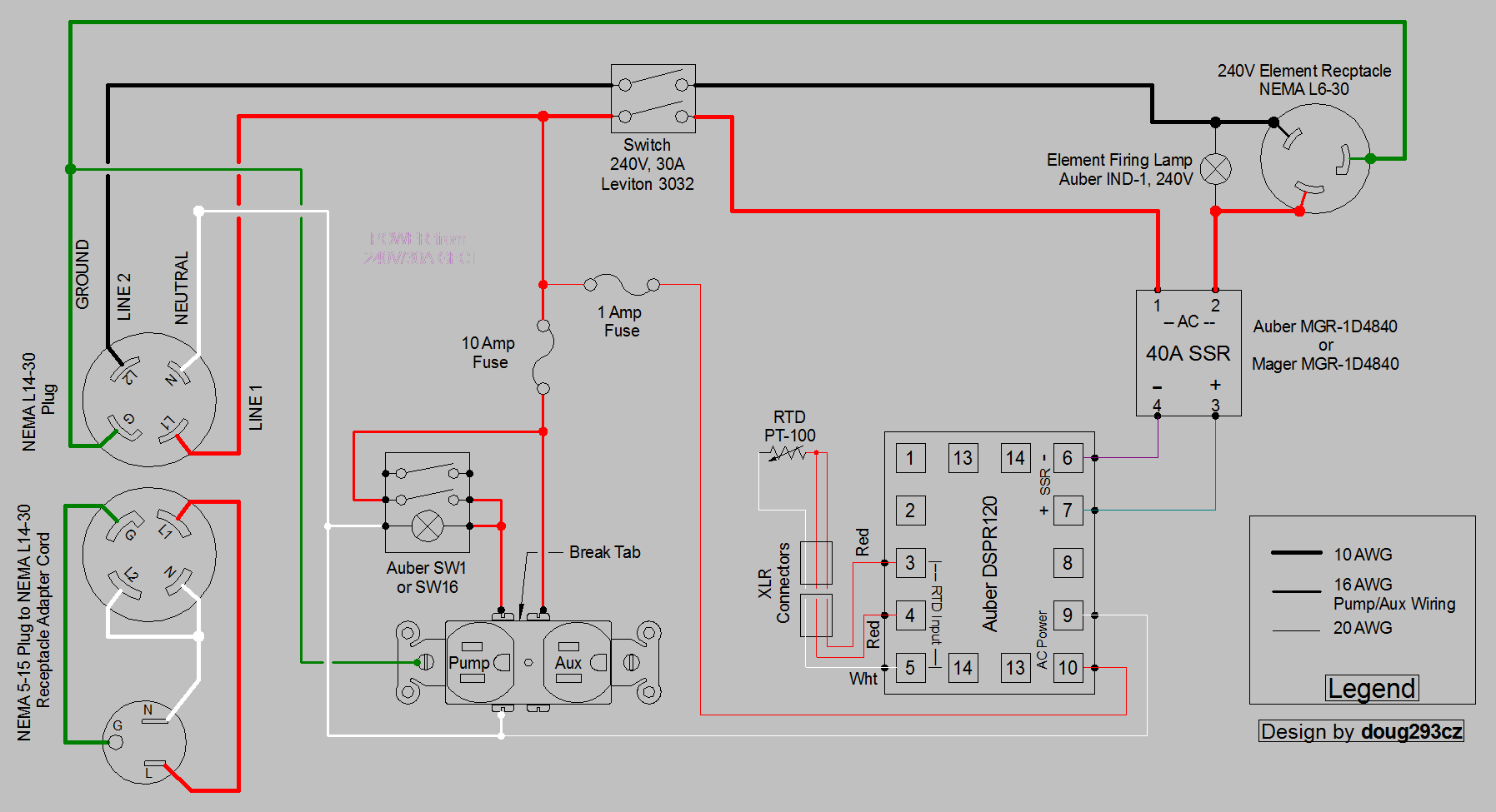
Here's a couple of ways to do it:

DSPR120 1-Pump 1-Aux Dual Voltage Input.PNG


DSPR120 1-Pump 1-Aux Dual Voltage Input contactor.PNG


Brew on :mug:
 
Thanks ajdelange and Doug, it looks like you described the same thing.

The first diagram actually looks like how my box is already wired. The only difference is the receptacle adapter cord. Am I ready it correctly that the cord would be the only difference?

Of course, I will go through all my wiring before plugging anything in, but I don’t see any additional switch or anything, and in my head I thought it all came down to the input power, but I just want to make sure I’m ready this right since it’s 5am and my brain might not be working right.
 
Last edited:
This is the Inkbird PID already wired up that I was talking about. Looks perfect to control a single 1650 watt element:

https://www.brewhardware.com/product_p/tempcontrol_ipb16.htm

It states it uses a PT100 sensor, but I am hoping to be able to change the receptacle to a RTD so I can use my existing tri-clamp temp sensor.
pt100 IS an RTD sensor... yes you can swap them just fine, others have already done it. (if your sensor is 2 or 3 wire)

I have seen those inkbird pid prebuilt controllers for as little as $80 shipped on sale in the past..
 
pt100 IS an RTD sensor... yes you can swap them just fine, others have already done it. (if your sensor is 2 or 3 wire)

I have seen those inkbird pid prebuilt controllers for as little as $80 shipped on sale in the past..

Sorry, I meant with an XLR plug/receptacle. These look like they might have an 1/8” mini phone, is that right? I imagine it wouldn’t be too complicated to swap it out so all my equipment uses the same stuff.

But now they got me thinking about using 1 box again, haha. Since the EZBoil isn’t a true PID and says it doesn’t need to be tuned, it could function on both systems and I already have everything except the EZBoil unit and a power cord.

Back to the think tank to figure out what I’m going to do, but thank you guys for all the info, it’ll help me decide what’s best for my situation and in the future.
 
Thanks ajdelange and Doug, it looks like you described the same thing.

The first diagram actually looks like how my box is already wired. The only difference is the receptacle adapter cord. Am I ready it correctly that the cord would be the only difference?

Of course, I will go through all my wiring before plugging anything in, but I don’t see any additional switch or anything, and in my head I thought it all came down to the input power, but I just want to make sure I’m ready this right since it’s 5am and my brain might not be working right.
Yes, it's just the plug/voltage adapter pigtail that makes it work. However, you do have to run any 120 volt loads (pumps, LED's, contactor coils, etc.) from the hot line that doesn't become neutral with the pigtail.

Brew on :mug:
 
I've been thinking of something similar. I've found adapters that go from 5-15P to L14-30R. The ones I've seen so far bridge the hot across L1 and L2, I think they are mainly used for generator transfer setups. I've also seen some for power supplies but I'm not sure if they bridge the hot or just provide power to L1. From what I can see, I don't see any standard adapters that take the neutral to L2, granted there aren't a lot of adapters out there.

Something to think about that may make things more "up to code" is installing a L14-30R on the kettle output. This does require changing some things. When you make the cables for the panel to kettle, you would need to make two different cables, one that would be for 240v and another for 120v both wired differently. Technically, the L6-30 is a 240v configuration not 120v.

A lot of wiring is trying to prevent the person from doing something stupid. I know that if you run a 240v element on 120v power, you get 1/4 of the wattage. Just curious, what happens if you'd do the opposite and run a 120v element on 240v. Would it produce 4 times the power or fry the element?
 
Thanks for the information. I did inquire about another off the shelf 5-15 to L14-30 adapter and it looks like it bridges both hots L1 and L2 to energize a transfer switch.

Thinking out loud, if one were to use one of these cables, and if they made the mistake of having the element plugged in to L1 and L2, basically wiring not changed, I'm guessing the element would not like the 120v single phase going to it for either a 240v or 120v element.

If you would use one of these off the shelf cables vs a custom one, I'm wondering if there is a way to electrically know you have bridged 120v hot coming in on both L1 and L2. If there was a way you might be able to trigger a relay to prevent something bad happening.
 
If a cord bridged L1 to L2, then measuring between L1 and L2 on the load side would yield zero volts. That's going to be useless inside a device that expects 240V between L1 and L2.

Brew on :mug:
 
Back
Top