notorious PID fermentation temperature control

Homebrew Talk - Beer, Wine, Mead, & Cider Brewing Discussion Forum

Help Support Homebrew Talk - Beer, Wine, Mead, & Cider Brewing Discussion Forum:

This site may earn a commission from merchant affiliate links, including eBay, Amazon, and others.

mboehm

Member
Joined
Sep 30, 2011
Messages
13
Reaction score
1
Location
Jamaica Plain
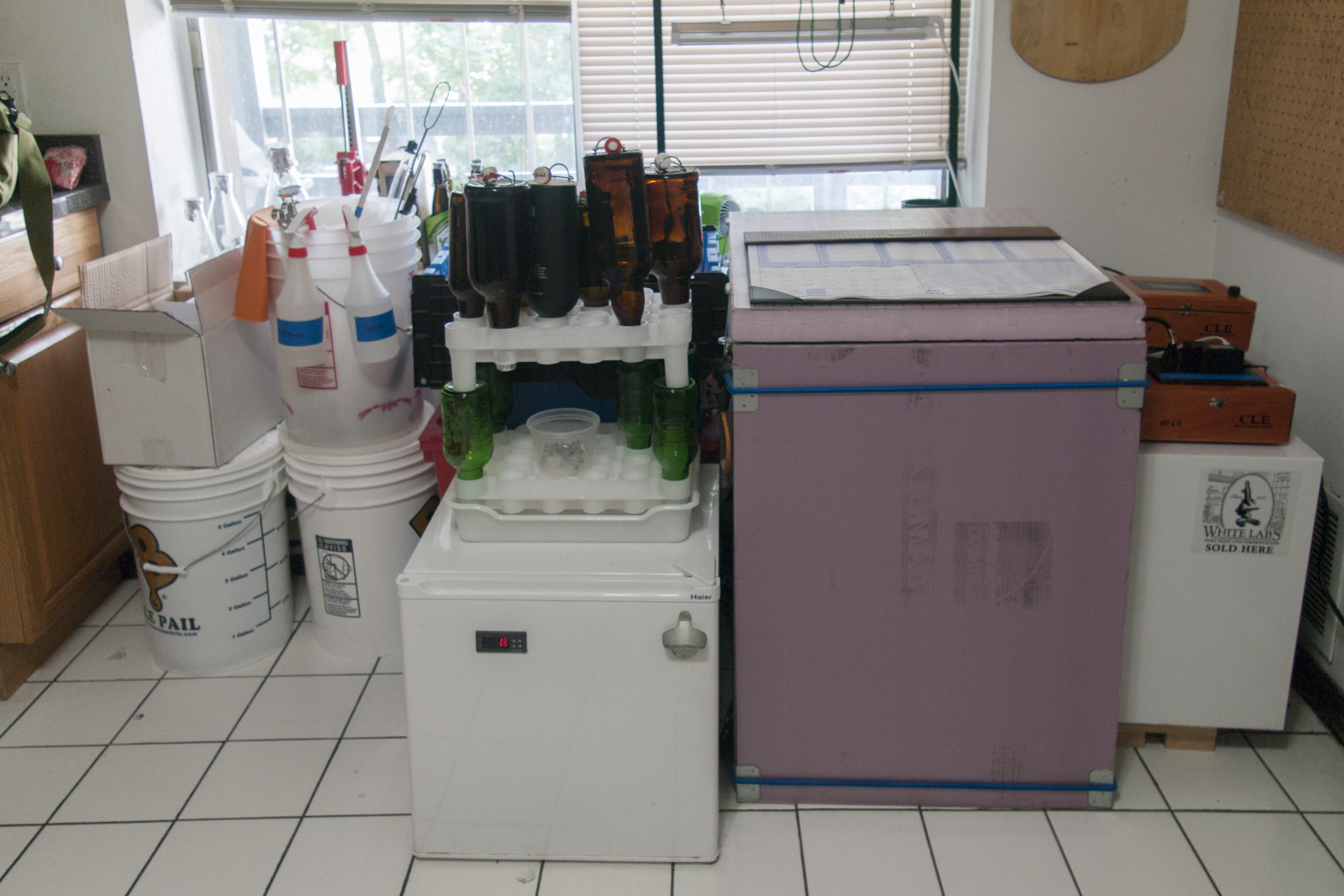
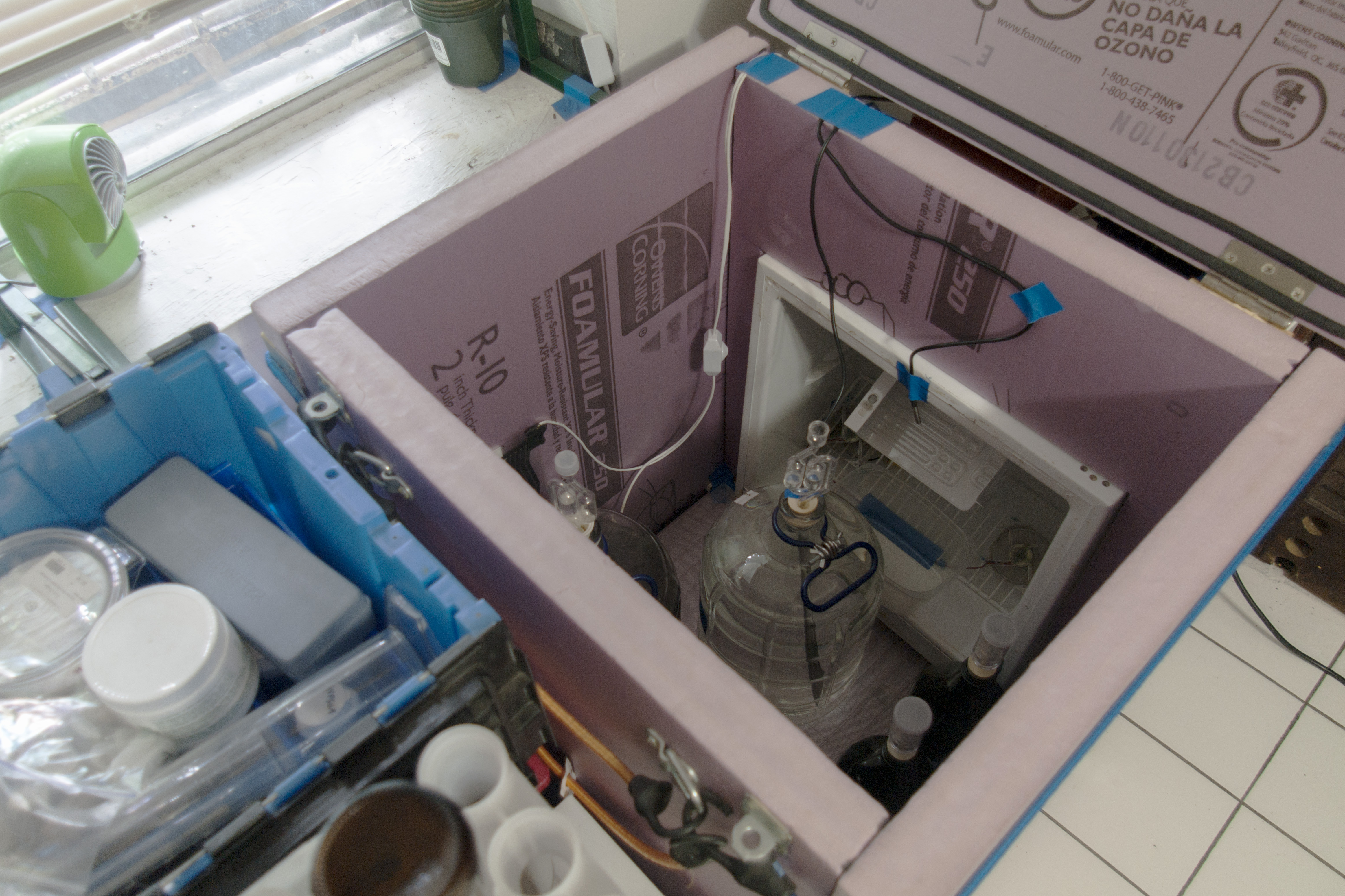
Hey guys! A while back I was inspired by some of the DIY write-ups on here and built my self a little fermentation chamber constructed of solid foam insulation and a diminutive 1.7 cu.ft dorm fridge I wrangled for free. Probably not something I could ever lager in during the summer, but good enough for my needs. That was about a year ago now, and I have done numerous successful batches in it. Previously I had been getting by on simple differential control with the love unit I had wired up with a probe stuck on the carboy side and insulated some. This had been working fine but I wanted a little finer control and was also looking for a little bit of a challenge.

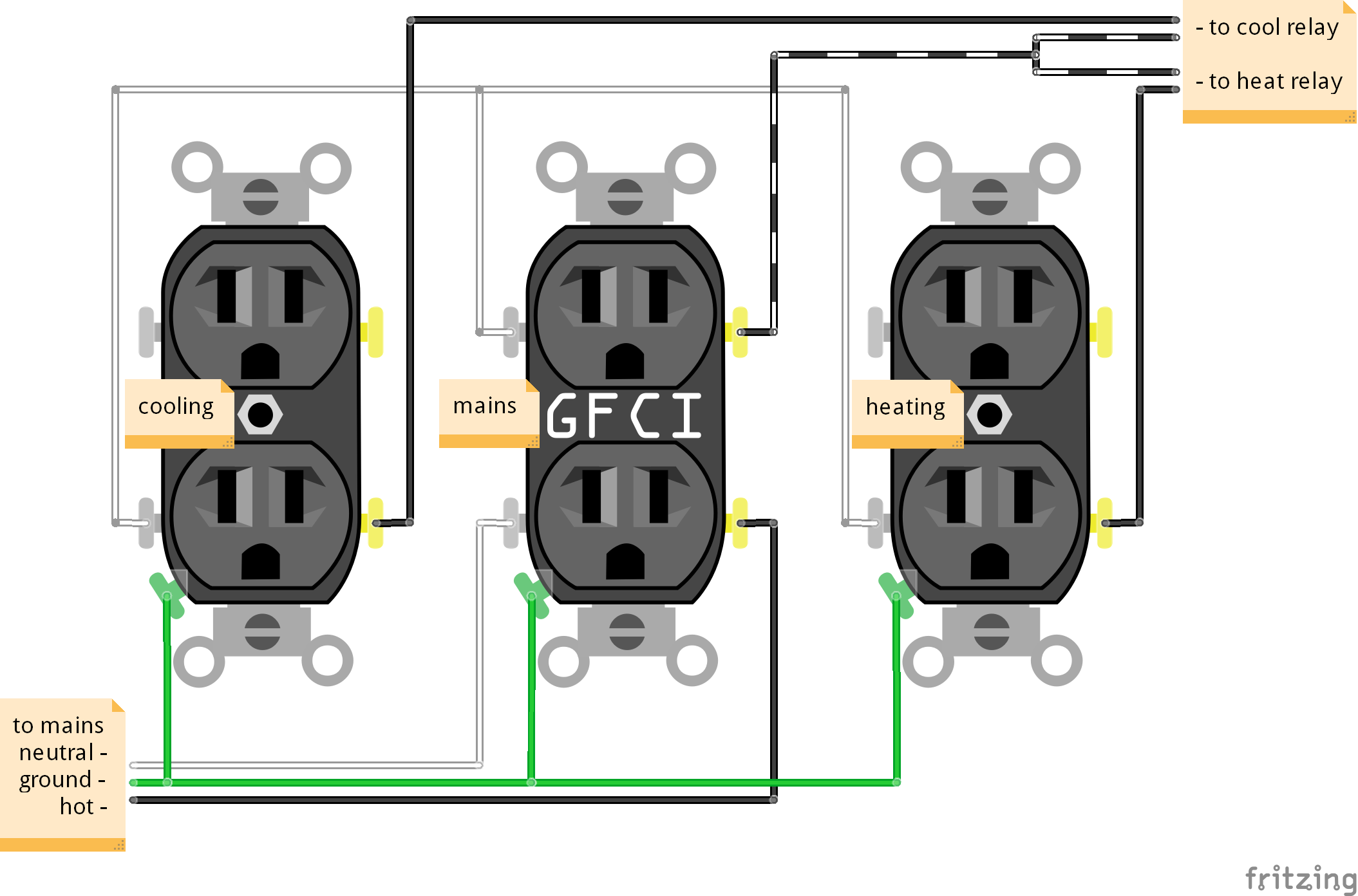
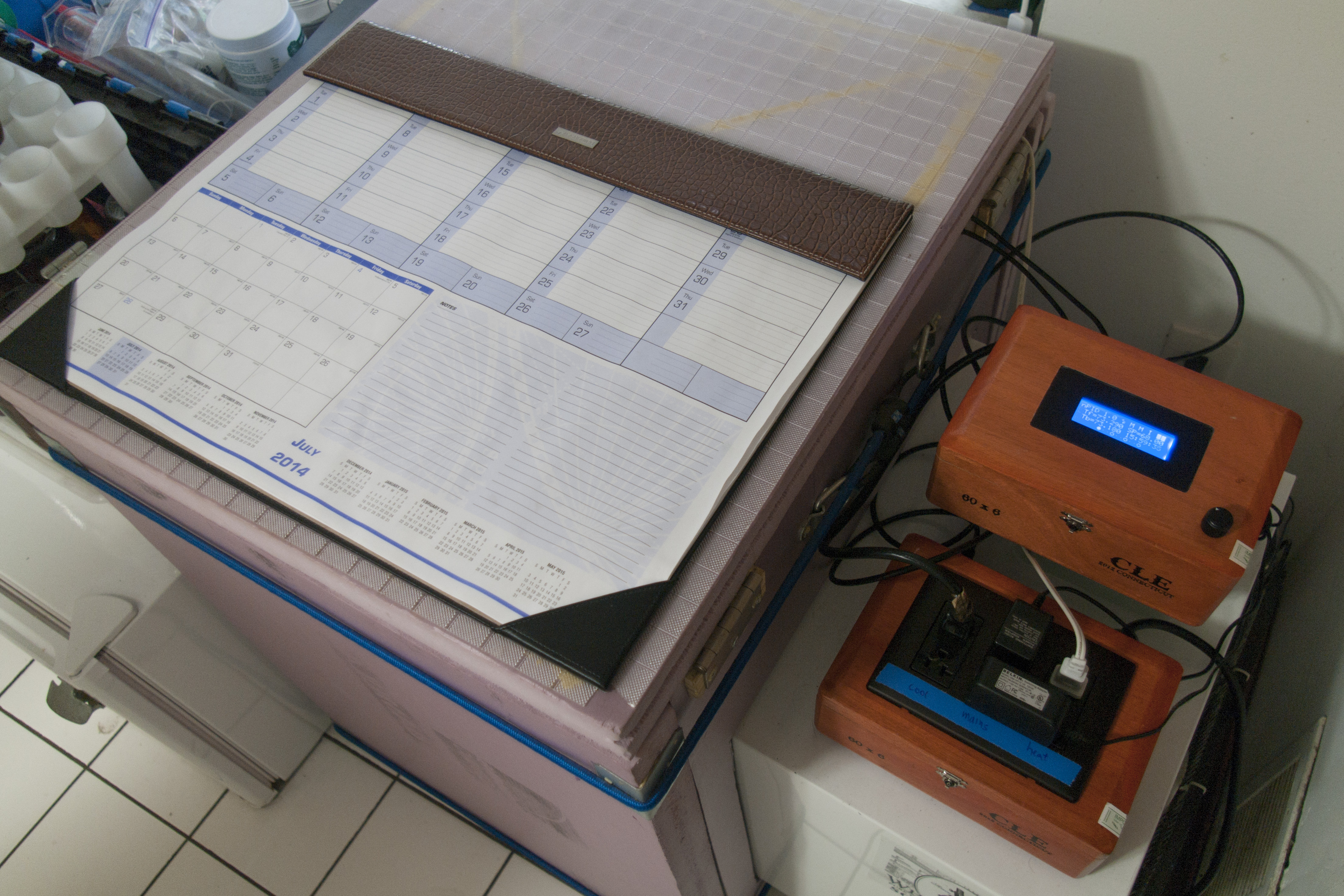
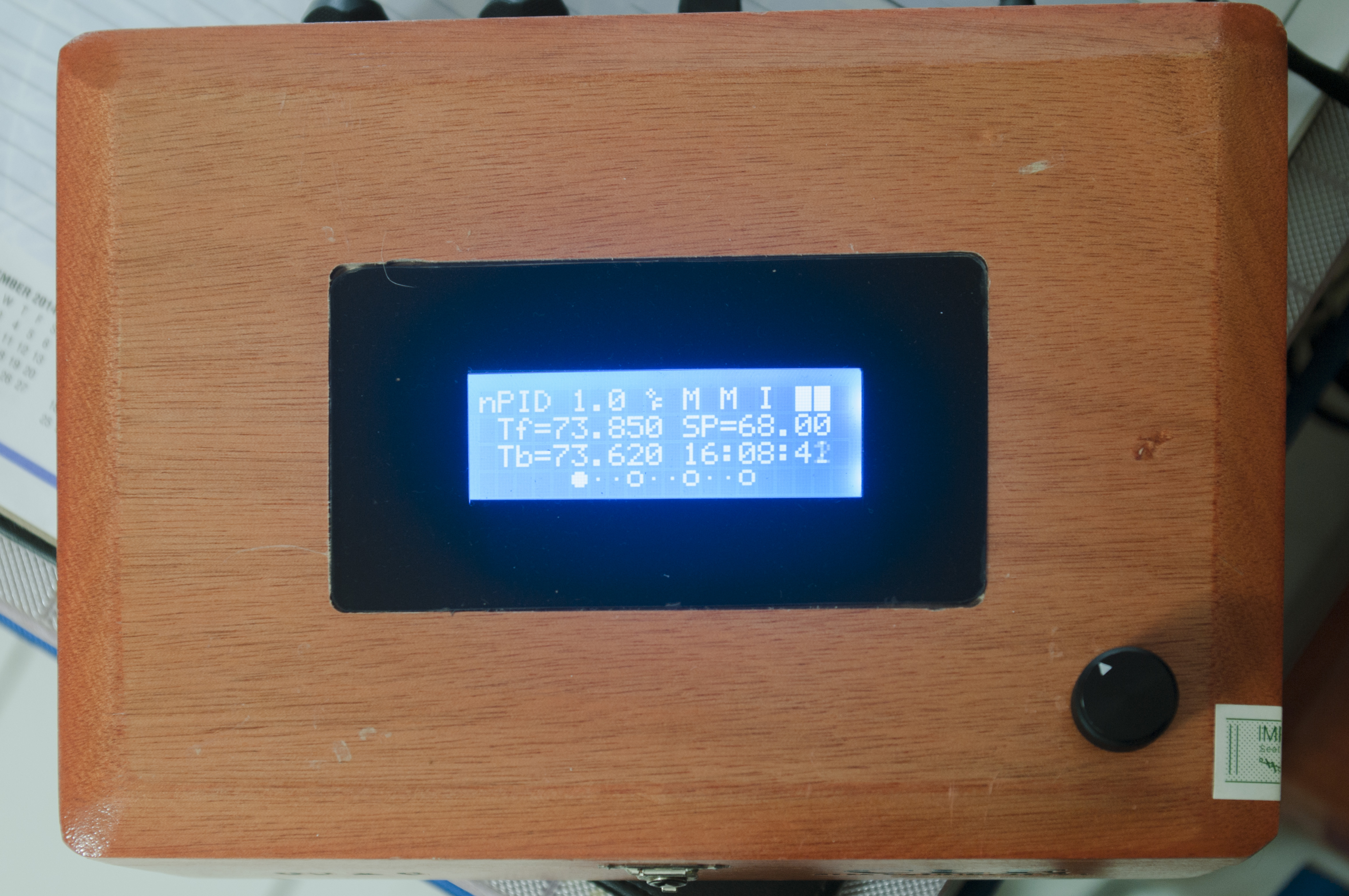
Over the last couple months I have been coding my own open source temperature control program for the Arduino MEGA 2560. I call it notorious PID. It incorporates a 20x4 character LCD for display, a rotary encoder with pushbutton for user input, Dallas OneWire DS18B20 temperature sensors, and a unique control algorithm inspired largely by the work of Elco Jacobs on UberFridge and brewPI. It also has data logging capabilities and supports end-user made CSV temperature programs (lists of steps: run at X temp for Y duration) via an SD card slot. This makes it possible to create custom temperature profiles for different fermentations that include things like temperature ramping, diacetyl rests and cold crashing. For a more complete description, check the README at my GitHub repository.

Most of my work the last couple weeks has been focused on tweaking the control algorithms and determining various tuning parameters (unique to each chamber/fridge/freezer). This is not a simple case of wiring my fridge to alarm outputs on a commercial PID. This is legitimate control that can efficiently maintain a desired setpoint within ~+/- 0.1 deg C. I'm pretty happy with this little project so far. There are a few small bugs that do not affect overall performance that I have to clear up. Until I do so, I've currently released it as prerelease v0.9.0 on GitHub. Pics of my setup to come.

notorious PID source via GitHub
 
Looks interesting... you had my interest with PID, Arduino, rotary encoder with push button and LCD screen - as I am looking to do something similar for a RIMS tube build so am hoping I can repurpose some of your open source code to reduce the work required :D I'm looking to implement it on an Arduino Mini Pro.
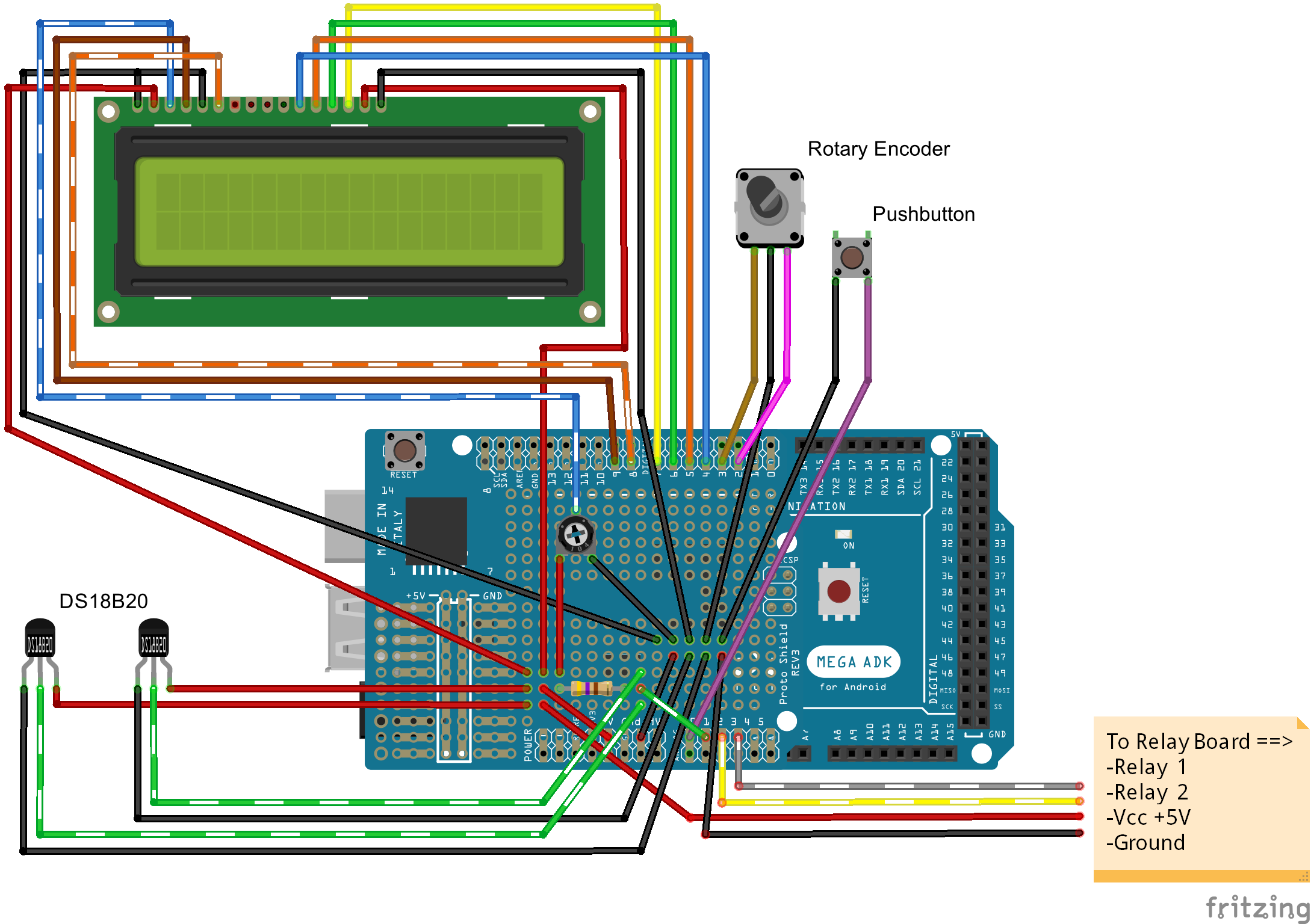
Looking forward for pictures!
 
I like this idea and I actually started to go down this road myself before the stc-1000+ project.
I second that the mega 2560 seems overkill, I'm guessing that is what you have at hand. The pro mini would be good, and maybe use an i2c lcd adapter to save some pins and complexity.
I actually wrote some code to handle profiles on the AVR side for brewpi, it also does ramping (linear, smoothstep or smootherstep, all using integer arithmetic), you should look into that (it's on my github).
I havn't really dug into your code, but I'd suggest you move your multiple .ino files into .cpp and .h files and just use one .ino. Also just looking at the bitmask of the program state variable hurts my brain, I'd suggest at least using defines for the masks so it is easier to read.
Keep it up! I think you are on to something!
 
To be honest, I originally started with an Arduino Uno R3. Early on I had problems with limited SRAM space. My program uses a half dozen or so libraries with fairly large footprints (SD is a hog). By the time I had implemented about half of the features I was running out of ram and the SD library was returning null on file open commands as a result. Granted I don't really need all the extra I/O, but by this point, the code is too large to fit in the flash space of the Uno anyway and to be fair, I'm trying to do nearly as much as brewPI without the microcomputer.

Of course if it is possible to fit it on a smaller board, I'm totally down for any suggestions but I think I'd have to ditch the SD or something. I've probably gotten at least some performance savings in switching from the DallasTemperature library to my own code that is specific to the DS18B20. I have a decent grip on code writing, but I am admittedly merely an amateur.

Some defines for the bitflags are a good idea. I will definitely take a look at your work. Something I really want to learn some more about is the bitshift filter implementation in brewPI. I am still using the standard butterworth filter from UberFridge for which there are numerous coefficient calculators online. I know to avoid floating point math on the arduino as a general principle, but I've been getting by just fine speed-wise with it.
 
Speed is not the biggest issue with floating point (unless you really need every clock cycle), but it eats up a boatload of codespace.
I haven't worked all that much with the SD library, but if it's a wrapper for FATFS (which I think it is) or aleast somewhat sanely written, then RAM usage can be reduced massively by configuration.
IMHO, what you are trying to do should absolutely be possible with a 328 based arduino.
In STC-1000+, I use a leaky integrator filter (mostly because that is all than can be afforeded), but it works pretty well. Filtering the temp data is very useful, but it should be pretty easy as well, as the temperature changes we are interested in are pretty slow, so you can low pass filter pretty hard.
 
^Thanks for the tip! I will look into it. In the meantime I now have a wiring diagram up; a little something I threw together in fritzing. There are a couple limitations with Fritzing/my skill that have been noted in the GitHub readme. This was about as clear I was able to make it on a first pass.


Pics of the setup yet to come!

edit:seems to be a server down over at github...hoping the image will return shortly
edit:yay! seems to be back up.
 
Update: I've just added a schematic for the power wiring.

My project utilizes a GFCI outlet that is wired so that it is able to provide ground fault protection for the whole project. Mains enter through the LINE side of the GFCI and the rest is fed off the LOAD side. Relays interrupt the HOT lines feeding the two ancillary outlets (safer and preferable to interrupting the neutral lines). The power outlets are a custom part I made for Fritzing.

 
It's photo time!

The chamber is constructed of 2" thick solid foam insulation. Cooling is provided by a diminutive 1.7 cu. Ft. dorm fridge obtained for free. Heating is provided by a bit of aging flexwatt also obtained for nil. There are a pair of 80mm CPU fans for air circulation. I've seen similar builds elsewhere on here that were glued together for a more permanent installation. I'll be moving at the end of the month and I built the chamber with this move in mind. I installed a couple of hooks on the front and back and bungees hooking into these are what hold it all together. The lid is hinged with a pair of hasps for locking it down. Gorilla Glue is perfect for use on this kind of foam and with clamps gives a strong bond. In one of the shots you can see a double wall of weather stripping along the inside lid of the chamber. Intersecting faces of the walls also have this stripping to create a reasonably airtight seal.

The second fridge in the overall shot of the space is not part of the chamber (it houses my culture library).

The temperature controller is housed in a pair of cigar boxes purchased for cheap on eBay. An ethernet cable with RJ45 connectors connects the two boxes. Logic circuitry has been isolated as much as possible from high voltage power circuitry. The LCD resides behind black vinyl masking on 1/8" acrylic that sits flush into the top of the box and also hides the LCD's mount screws.


Loved the project!!!
Was just starting to think on something myself. On your part list, as I live in Brazil, I can't buy the Adafruit data logging shield. What would be the substitute for it?
Cheers,
Luis
 
If you don't have access to the adafruit components you may be able to find something comparable from another arduino-board-making company. Or you may be able to assemble a similar board yourself. I know the SD card slot and the RTC are available individually but you will have to know a bit about how to wire them up and do the soldering yourself (it may involve surface mount soldering which can be a delicate task). So long as the same i/o numbers are used as in my project, the code should work.

Alternatively, you may be able to simply skip it all together and leave out the data logging capability. It is non-essential to the core functionality of the PID. This will require some modification of the code however so a working knowledge of C++ and the arduino environment would be necessary.

Sorry I cannot be more helpful than that! This is my first arduino project so my knowledge of what is available is pretty limited. Good luck!
 
Hi, I was able to get a data logging shield from China and I'm ready to start the project. Could you provide a picture of the assembled boards as the schematic is not so clear :))))
Thanks,
luis
 
Back
Top