• Please visit and share your knowledge at our sister communities:
  • If you have not, please join our official Homebrewing Facebook Group!

    Homebrewing Facebook Group

Need advice: Correct load for relays?

Homebrew Talk

Help Support Homebrew Talk:

This site may earn a commission from merchant affiliate links, including eBay, Amazon, and others.

Bruer

Member
Joined
Oct 29, 2017
Messages
9
Reaction score
1
Hi all,

I'm in Australia where the standard house circuits (in our rental place) are 240v nominally 10A (with 16A fuse) with twin and earth.

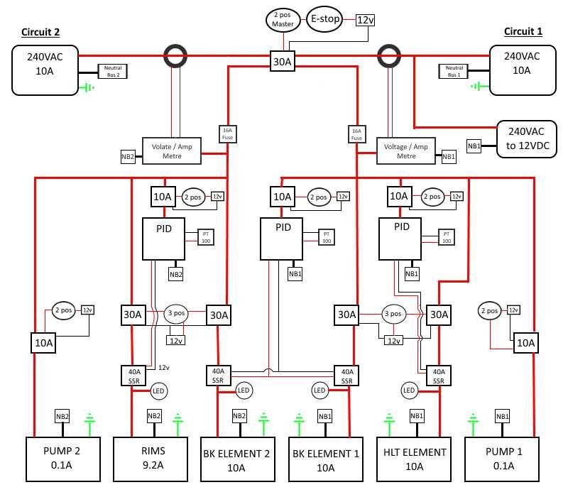
I'm putting together a electric 3v RIMs system. My system uses two inputs for separate circuits in the house. My system uses 12vdc switches and mechanical relays to switch all of the AC circuitry. Not shown on this image is that the RIMs element switch will be interlocked by a pump to prevent dry firing.

My question is: what sized mechanical relay do I need to use for switching the 2200w heating elements? Will a 10A suffice or do I need to use a larger relay?
received_10156403867368627.jpeg
 
10A would be the minimum and should be fine as long as they are each on one element. A 15 or 20amp would be ok also. Sometimes I find the 20amp relays are actually cheaper if you shop around. A 2200watt element draws 8.3 amps at 240v. I would recommend solid state relays (ssr) rather than mechanical. They hold up longer to the constant switching. Any mechanical relay that would hold up would be quite a bit more expensive. Not to mention loud! The constant clicking gets old. The solid state relays are silent.
 
... I would recommend solid state relays (ssr) rather than mechanical. They hold up longer to the constant switching. Any mechanical relay that would hold up would be quite a bit more expensive. Not to mention loud! The constant clicking gets old. The solid state relays are silent.
OP is using SSR's for the power modulation switching.

Brew on :mug:
 
You really don't need the power switches to turn the PID's on separately from the master power relay/contactor. As a bonus, if the PID's come on when the master power relay/contactor is energized, you get free power on indicator lights with the PID displays.

Brew on :mug:
 
Yes. I'm using 40 SSRs to modulate the element on/off from the PID. The constant switching is too much for mechanical relays and generates a lot of heat. These need to be larger and attached to a heatsink.

My question was not perhaps as clear as it should have been. I'm asking if a 10A mechanical relay is suitable to switch the element on/off? Modulation would controlled by the PID and SSR. Do heating elements spike their load when initially turned on or are they a purely resistive load (drawing the full 9.2A straight away)?
Heating elements are pretty much purely resistive.

Brew on :mug:
 
Hey guys, it's an old thread and I've taken all the advice on board and am well on the way to completing the wiring.

Just a quick question. Because I need to use two household circuits (separate cicuits), is it proper and safe to run all of the earths into the same bus?
 
Hey guys, it's an old thread and I've taken all the advice on board and am well on the way to completing the wiring.

Just a quick question. Because I need to use two household circuits (separate cicuits), is it proper and safe to run all of the earths into the same bus?
Yes, you can use a common ground bus. But you need to keep the neutral buses separate, as you show, so that any leakage protection circuit can operate properly (not sure what the Aussie equivalent of a GFCI is.)

Brew on :mug:
 
Yes, you can use a common ground bus. But you need to keep the neutral buses separate, as you show, so that any leakage protection circuit can operate properly (not sure what the Aussie equivalent of a GFCI is.)

Brew on :mug:
Thanks for that. Neutral buses are separate. Will use a single common earth bus. FWIW, GFCI is mandatory for all domestic electrical supply panels.
 
The rims in my 3 barrel brewpub setup consists of (2) 2200w 240v cartridge heaters and it flickers between 19-20amps draw on my amp meter but thats with the panel and I believe the riptide pump possibly running off the same circuit (my control panel is fed by 2 separate 60a lines so not sure on the pump without looking) each 2200w element is on its own 10a breaker which has never tripped if it helps. I do use larger 30a rated din contactors for element power switching, I think its just a bit more reliable then maxing out those 10a relays. (I do use 10a relays to switch the 30a relays though since im controlling everything via arduino and brucontrol.) You obviously will be using switches.

BTW If it helps, I use the NO /NC contacts of the relays to prevent too many elements from being on at the same time because I have 8 5500w elements as well as the rims elements and in addition to only 4 of the 5500w elements being allowed to be on at once I have it setup so one of the 4 HLT elements kicks off if the rims is on. Technically this isnt needed since I have 120a but I build it to stay below 100a because thats the max of my 2 50a amp meters.
 
Last edited:
Back
Top