OP
OP
TheFlyingBeer
Well-Known Member
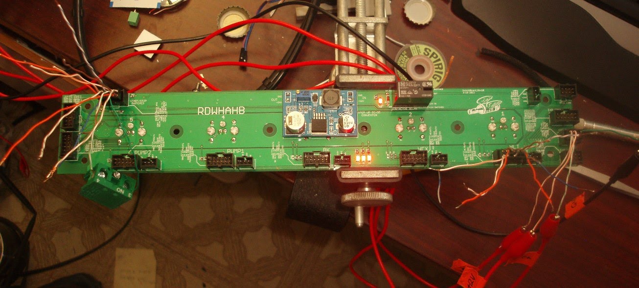
The LCD key/switch breakout panel is working like a champ during my bench testing. This board breaks out 5 ports for the HLT, MLT, BK, Pump 1, and Pump 2 LCD keys. It also provides connections for the switches and dials for those same items. A 12VDC to 24VDC step up converter (blue board) provides power to turn the contactor on in the power control box. This 24V output is controlled by the black relay to the right which requires the following to be turned on:
1. All element/pump control switches are in Off position to initially energize (my safe start feature)
2. The emergency stop is not activated.
The red LED next to the relay shows that it is on. I tested both the conditions above and it works perfectly. The three other red LEDs at the bottom middle of the board indicate that it has proper +3.3V, +5V, and +12VDC supplies.
Next I have to make cables to connect between this board and the other 4 LCD keys and then wire up the switches and dials.


 SICK build!!!
 :rockin:


![Craft A Brew - Safale BE-256 Yeast - Fermentis - Belgian Ale Dry Yeast - For Belgian & Strong Ales - Ingredients for Home Brewing - Beer Making Supplies - [3 Pack]](https://m.media-amazon.com/images/I/51bcKEwQmWL._SL500_.jpg)


") Thanks for the reply. Happy brewin' to ya!
Thanks for the reply. Happy brewin' to ya!