• Please visit and share your knowledge at our sister communities:
  • If you have not, please join our official Homebrewing Facebook Group!

    Homebrewing Facebook Group

My Electric Brewery

Homebrew Talk

Help Support Homebrew Talk:

This site may earn a commission from merchant affiliate links, including eBay, Amazon, and others.
Can someone explain to me how terminal blocks work?

In my mind I'm hoping they work like a splitter. Like one hot leg can be attached then just plug in any wire that needs to branch off that hot leg.

Is that how they work?

I've seen a ton of them on eBay for cheap, but the descriptions seem to state they insulate one wire from another?

Would that mean I would need a jumper? Or what is the purpose of a jumper?

I want to use these terminal blocks if possible to make the innards of my panel nice and neat!

I cannot speak for how they are used in the panels but in a general electrical terms:

Terminal blocks are used for multi-tap connections to a shared source. The example most of us in the US can relate to is the ground and neutral bus bars in our breaker panels.

In certain parts of Europe, terminal blocks are used for all household connections. My favorites are the ones I used in Germany that push-in, 1/4-turn release. Instead of wire nuts terminal blocks are used in the fixture box.
 
Can someone explain to me how terminal blocks work?

In my mind I'm hoping they work like a splitter. Like one hot leg can be attached then just plug in any wire that needs to branch off that hot leg.

Is that how they work?

I've seen a ton of them on eBay for cheap, but the descriptions seem to state they insulate one wire from another?

Would that mean I would need a jumper? Or what is the purpose of a jumper?

I want to use these terminal blocks if possible to make the innards of my panel nice and neat!
Basically yes,

There are different styles... Some are broken up into segments and those would need jumpers to add more post /connection points to a single leg... some already have all the terminals joined into one since connected block...Some have removable jumpers that come with them..
 
I cannot speak for how they are used in the panels but in a general electrical terms:

Terminal blocks are used for multi-tap connections to a shared source. The example most of us in the US can relate to is the ground and neutral bus bars in our breaker panels.

In certain parts of Europe, terminal blocks are used for all household connections. My favorites are the ones I used in Germany that push-in, 1/4-turn release. Instead of wire nuts terminal blocks are used in the fixture box.

Basically yes,

There are different styles... Some are broken up into segments and those would need jumpers to add more post /connection points to a single leg... some already have all the terminals joined into one since connected block...Some have removable jumpers that come with them..
Sounds like I may be on the right path then with these.

Would either of you be able to point me towards something that would be what I am looking for?

I have found a couple options, but I am having a hard time telling if they need jumpers or not. I would PREFER to not have to use a jumper, but rather have it built in.

Here are a few examples:

http://www.ebay.com/itm/Beau-Vernit...410?pt=LH_DefaultDomain_0&hash=item27d5415dd2

http://www.ebay.com/itm/AC-300V-30A...646?pt=LH_DefaultDomain_0&hash=item35c3bf7ae6

http://www.ebay.com/itm/2-Single-Wi...698?pt=LH_DefaultDomain_0&hash=item4875b9bb52

The first one for sure. the other two are harder to tell by the pictures.
 
fyi the home depot and radioshack are good local sources that actually have pretty good prices on these... they both have multiple types and sizes... you should honestly have the best idea what you need for your setup since they are all different...I use only one in my DIY control panel in my signature...
 
fyi the home depot and radioshack are good local sources that actually have pretty good prices on these... they both have multiple types and sizes... you should honestly have the best idea what you need for your setup since they are all different...I use only one in my DIY control panel in my signature...

I will have to check out HD!
 
So what would be the cons of removing the key switch, key switch light, and associated coil from my panel design?

Now that I'm getting my parts together, I'm realizing I could really use the extra space by getting rid of the key switch, light, and coil. I'm a little short on both internal and external space in my panel.

If I am looking at this correctly, it seems that the e stop and key switch are kind of a redundant processes. Which I assume is the point. But I feel comfortable just using the estop as the main power source. Probably associate a light with the estop so I can tell when the panel is powered up.

Anyone think this is a bad idea? Or just personal preference thing?
 
for @deece

IMG_0925.jpg
 
Anyone think this is a bad idea? Or just personal preference thing?

There are long threads devoted to this exact question and there are 2 different camps, both with knowledgeable people supporting both sides.

I am in the camp that its redundant, serves no purpose and is just extra cost. I added a lockable disconnect to my system to serve this function.

I wouldn't fault you if you included it though. I'd just say you wasted time and money adding something that doesn't have any purpose. ;)

Fears = Calmed

This thing will be unplugged when not in use also.

Lockable disconnect?? Like an estop with a key?
 
There are long threads devoted to this exact question and there are 2 different camps, both with knowledgeable people supporting both sides.

I am in the camp that its redundant, serves no purpose and is just extra cost. I added a lockable disconnect to my system to serve this function.

I wouldn't fault you if you included it though. I'd just say you wasted time and money adding something that doesn't have any purpose. ;)

Could not agree more. Switch On/Off > PID > SSR > Element Plug Connection> The End.
 
Could not agree more. Switch On/Off > PID > SSR > Element Plug Connection> The End.

I would add a little to this.

Incoming Power: plug optional, use rotary disconnect switch. This is your main cut off. I used the Auber SWM-63. I don't recommend Auber for anything though due to a disgustingly poor customer service I had with them. Choice is yours though.

Power Circuit: Disconnect -> Circuit Breaker -> SSR -> Receptacle.
Controller Circuit: Disconnect -> Circuit Breaker -> Switch -> PID -> Switch* -> SSR

*A lot of the controllers automatically go into auto mode as soon as they get power. The second switch will allow you keep the SSR from firing as soon as the controller is powered, preventing a dry fire. I missed this on my initial design because i figured the PID had to have its own on/off switch, but it doesn't. I am going to go back and add this but right now i'm using the CBs to cut power off until i need it.
 
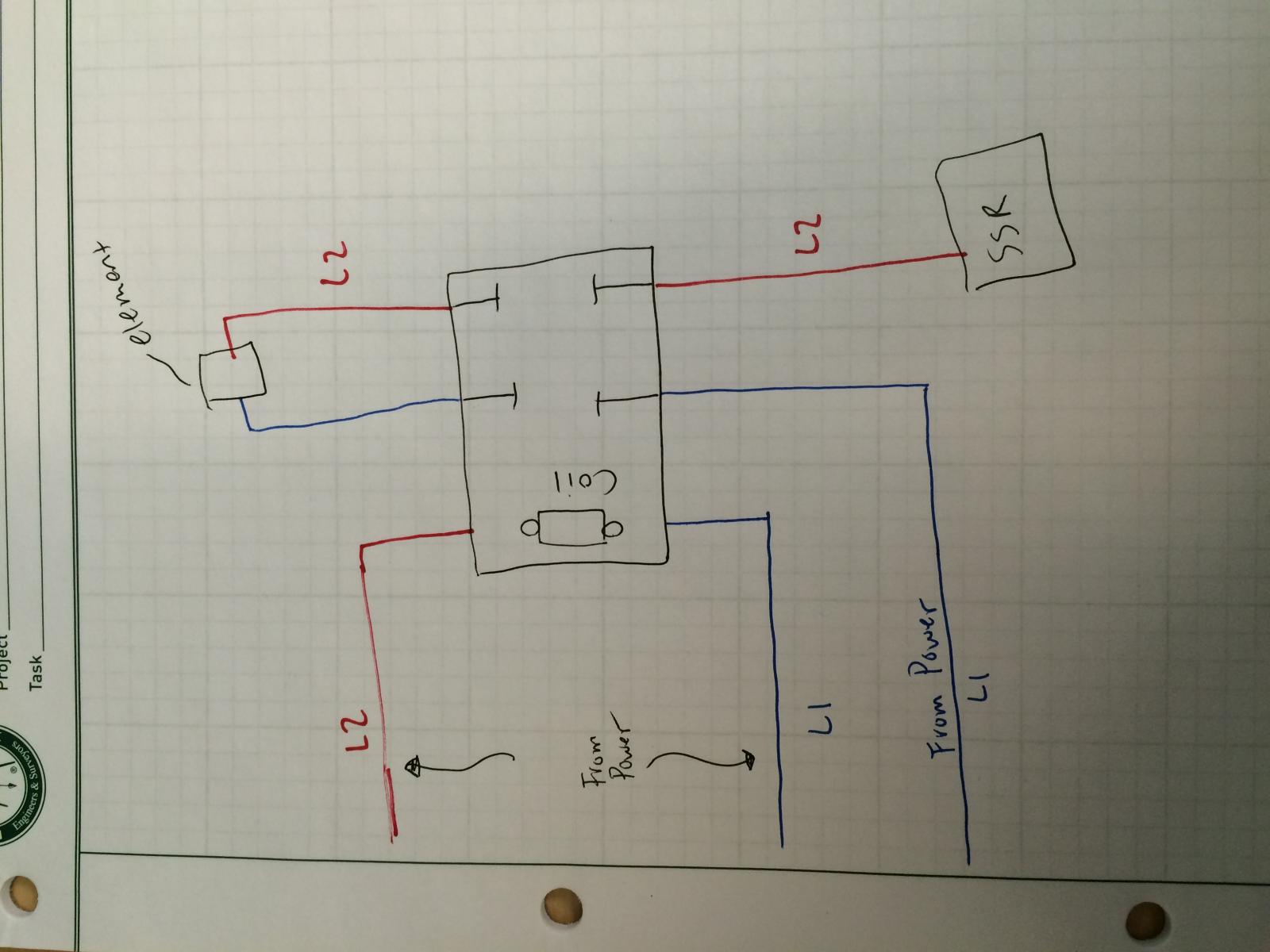
You would want a switch on either L1 or l2 going to the coil otherwise it would always be on. Also a feed going to the ssr. Hopefully someone more knowledgeable will chime in also.
 
Here's are some snippets from my AutoCAD schematic. I've never posted it before now...

panel power.png
PID Power.PNG
PID Power2.PNG
 
You would want a switch on either L1 or l2 going to the coil otherwise it would always be on. Also a feed going to the ssr. Hopefully someone more knowledgeable will chime in also.

I will actually have a 3 way switch to one of the legs and the other leg is coming from the ssr. sound right?
 
a legend is in the plans

as of right now the legend is in my head :)

You know there are standard electric device symbols out there, right?

Circuit Breakers
Fuses
Push Buttons
Selector Switches
Lights
Relays (Mechanical and SSR)
etc.
 
*A lot of the controllers automatically go into auto mode as soon as they get power. The second switch will allow you keep the SSR from firing as soon as the controller is powered, preventing a dry fire. I missed this on my initial design because i figured the PID had to have its own on/off switch, but it doesn't. I am going to go back and add this but right now i'm using the CBs to cut power off until i need it.


I'm glad you mentioned this! I never thought of this. I now will be adding a three way switch after my PID to switch between the two elements. I previously was going to have a 2 way so that I could just specify which element would be getting the power. But with the three way I can have it set to no element getting power but I can still have my PID on to make adjustments or what not.

Thanks :)
 
Sounds like I may be on the right path then with these.

Would either of you be able to point me towards something that would be what I am looking for?

I have found a couple options, but I am having a hard time telling if they need jumpers or not. I would PREFER to not have to use a jumper, but rather have it built in.

Here are a few examples:
]

Try looking at ebrewsupply.com, personally I find it easier and cheaper to buy the parts from him as opposed to those remaining radio shack stores. Look at his DIN hardware. Makes for a very clean looking setup as well. As far as eBay, I quit them after 15 years since I'd rather pay more and have something quickly than wait weeks for eBayChina parts to arrive.
 
Try looking at ebrewsupply.com, personally I find it easier and cheaper to buy the parts from him as opposed to those remaining radio shack stores. Look at his DIN hardware. Makes for a very clean looking setup as well. As far as eBay, I quit them after 15 years since I'd rather pay more and have something quickly than wait weeks for eBayChina parts to arrive.


I hear ya there man. Those ebay prices sure are mesmerizing, but it takes forever to get them! I'm not in much of a hurry, but I am going to be making sure I do it right.

I like his din stuff. I actually dream of having my cp lined with din rails and the nice neat wires inside. Just got to make sure that dream aligns with my wallet!!! Ha

Radio shack is still around? Haha jk
 
I will actually have a 3 way switch to one of the legs and the other leg is coming from the ssr. sound right?

No... the coil power in the relay is switched with your 3 way switch... the actaul relay contacts have both actual heavy hot (L1 and L2) going through them before one of those wires goes through the ssr.... The ssr + and - wires should go right to your pid....
 

Latest posts

Back
Top