• Please visit and share your knowledge at our sister communities:
  • If you have not, please join our official Homebrewing Facebook Group!

    Homebrewing Facebook Group

List of PJ Electrical Diagrams

Homebrew Talk

Help Support Homebrew Talk:

This site may earn a commission from merchant affiliate links, including eBay, Amazon, and others.
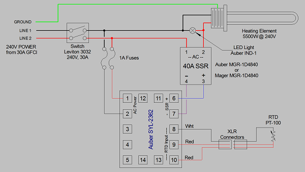
thanks everyone... now, the next question...using the diagram I posted above... will this SSR be wired just like it looks in the diagram? It doesn't have the "1-2-3-4" but instead has "L1-L2-T1-T2"...

NO. This is a dual SSR (two SSR's in one package.) The screw terminals are all AC power connections. The left side is for one SSR, and the right side for the other. The DC control signals go to the pins near the bottom center (above the mounting hole.) I don't know which pins control which SSR, or which are plus or minus. It may be marked on the body somewhere (like the AC connections are), or you may have to look for the information on the interwebs.

Edit: Looking harder at the pic, the control signal pins are marked (just above the pins.)

Brew on :mug:
 
thanks again. I wondered what the pins were... I guess they require special connectors...maybe I should just pick up a regular MGR-1D4840?
The pins are marked from top to bottom with -/+ 2 on top pair and -/+1 on the bottom pair.
Bob

NO. This is a dual SSR (two SSR's in one package.) The screw terminals are all AC power connections. The left side is for one SSR, and the right side for the other. The DC control signals go to the pins near the bottom center (above the mounting hole.) I don't know which pins control which SSR, or which are plus or minus. It may be marked on the body somewhere (like the AC connections are), or you may have to look for the information on the interwebs.

Edit: Looking harder at the pic, the control signal pins are marked (just above the pins.)

Brew on :mug:
 
thanks again. I wondered what the pins were... I guess they require special connectors...maybe I should just pick up a regular MGR-1D4840?
The pins are marked from top to bottom with -/+ 2 on top pair and -/+1 on the bottom pair.
Bob

I have never actually had one of these dual SSR's so can't be sure of what size the pins are, but would be very surprised if they were anything other than 0.025" square pins, as these are pretty standard. If they are 0.025" sq pins, you can connect to them with "DuPont" connector jumpers. Just cut the connector from one end, solder to the SSR signal wire coming from your temp controller, and protect the solder junction with some shrink tubing.

Brew on :mug:
 
Last edited by a moderator:
OK...so I found an old computer with a nice RGB 4 pin connector that fits the SSR pins ... which 2 screws on the SSR do I use? the top 2 are marked L1 and L2, the bottom screws are marked T1 and T2. Then, which of the 4 pins do I run to the PID?
thanks!
 
OK...so I found an old computer with a nice RGB 4 pin connector that fits the SSR pins ... which 2 screws on the SSR do I use? the top 2 are marked L1 and L2, the bottom screws are marked T1 and T2. Then, which of the 4 pins do I run to the PID?
thanks!

Everything marked "1" goes with one SSR (L1, T1, etc.), and everything marked "2" (L2, T2, etc.) goes with the other SSR.

Brew on :mug:
 
thanks again... does it matter which way the SSR is wired as far as the T1 and L1 (input/output wise) ?
 
got it... I will attach the energized wire coming from my switch to the L1 terminal, and the wire going from the SSR to my heating element will be connected to the T1 terminal. I will run from the DC "1+" SSR post to the #6 terminal on the PID and the DC "1-" will go to the #7 terminal on the PID...
thanks again. I owe you all a cold one.
:mug:

1-PID%201-Element%200-Pump%200-Aux%20240V%20only%20simple.PNG
 
Now that I have finally settled on my eBrew setup I see that I was a bit too late to utilize PJ's drawings. I managed to save a few but they where the Rims versions and I have decided ultimately on a Herms set up. The closest I could find was the one attached below however I am thinking I could modify it to use the DPSR120 EZ boil and switch the mash and boil functions to control the HLT for mashing and then the BK during the boil with the dial adjust. I would just need to switch the rtd probe from the mash recirc to the boil kettle. The HLT pid would just get my strike water to temp effectively. Eliminating the separate MT Pid (and Timer, not needed)would save a few bucks and fit in the 12 X 12 enclosure I already purchased from Auber

Basically;

HLT Pid (SYL-2532) controls HLT strike water
MLT/Boil (DPSR-120) with switch control for Mash control and Boil Kettle for Boil

Does anyone see an issue going this route and any chance someone has a diagram closer to what I have eliminating the MASH Pid?

LTB 30 amp eBrewery schematic.jpg
 
Now that I have finally settled on my eBrew setup I see that I was a bit too late to utilize PJ's drawings. I managed to save a few but they where the Rims versions and I have decided ultimately on a Herms set up. The closest I could find was the one attached below however I am thinking I could modify it to use the DPSR120 EZ boil and switch the mash and boil functions to control the HLT for mashing and then the BK during the boil with the dial adjust. I would just need to switch the rtd probe from the mash recirc to the boil kettle. The HLT pid would just get my strike water to temp effectively. Eliminating the separate MT Pid (and Timer, not needed)would save a few bucks and fit in the 12 X 12 enclosure I already purchased from Auber

Basically;

HLT Pid (SYL-2532) controls HLT strike water
MLT/Boil (DPSR-120) with switch control for Mash control and Boil Kettle for Boil

Does anyone see an issue going this route and any chance someone has a diagram closer to what I have eliminating the MASH Pid?

Seems like you would want to switch between two temp sensors on the controller for the HLT element. One in the HLT for heating strike/sparge water, and the other in the MLT to control mash temp. Otherwise, you need to figure out ahead of time what HLT temp to set to maintain your desired mash temp, and the offset would likely change for different batch sizes. Either way you need to be able to measure the temp in the MLT during the mash. I would use an EZBoil for both the HLT and BK element control. An interlock to make sure the HERMS recirc pump is on when controlling the mash temp might be a good idea. One concern with switching sensors on a single controller, is that the sensors may need different offset adjustments. I would input the offset for the MLT probe into the controller, and then just determine what the error for the HLT probe is at that offset, and figure that in when setting the temp for strike/sparge water.

Brew on :mug:
 
I have never actually had one of these dual SSR's so can't be sure of what size the pins are, but would be very surprised if they were anything other than 0.025" square pins, as these are pretty standard. If they are 0.025" sq pins, you can connect to them with "DuPont" connector jumpers. Just cut the connector from one end, solder to the SSR signal wire coming from your temp controller, and protect the solder junction with some shrink tubing.

Brew on :mug:

I use dual SSRs (crydom) in my system. Those connectors are 0.1" pitch .025" pins, as you described.
 
Last edited by a moderator:
so... what is the best way to attach the smaller diameter wires to the large wires for things like the fuses and the indicator light?
thanks!

attachment.php

this is a long thread to wade through... is this diagram the simplest one for a PID controlled BIAB system? also, does one exist with pump control for recirculating? i think it would be relatively straightforward to split off the feed for line 1(before the switch) and ground to complete this circuit separately with a switched outlet, but wanted to doublecheck...
 
this is a long thread to wade through... is this diagram the simplest one for a PID controlled BIAB system? also, does one exist with pump control for recirculating? i think it would be relatively straightforward to split off the feed for line 1(before the switch) and ground to complete this circuit separately with a switched outlet, but wanted to doublecheck...

You could leave out the Element Firing LED indicator lamp, but then you could miss out on an SSR failure (they tend to fail in the on state.) You could also leave out the fuses if you use 10AWG wire to deliver power to the PID. By the way, this is one of my designs.

Here's the one pump version of the drawing, which also uses a newer, better controller.

DSPR120 1-Pump Simple.jpg

Note that adding a 120V pump requires a four wire power feed vs. the three wire feed used by the 240V only (no pump) design.

Brew on :mug:
 
Seems like you would want to switch between two temp sensors on the controller for the HLT element. One in the HLT for heating strike/sparge water, and the other in the MLT to control mash temp.

Exactly! Most setups I have seen take the mash temp from the HLT tank and adjust. I want to eliminate the extra PID (Mash) and use the DPSR-120 control for the Mash taking temp from the mash but controlling the HLT element. Then use a switch to apply control voltage from the DPSR-120 to the Boil Kettle. With that set up I would need to move the temp probe from the mash tun to the boil kettle.

Just bouncing the idea off anyone listening.
 
You could leave out the Element Firing LED indicator lamp, but then you could miss out on an SSR failure (they tend to fail in the on state.) You could also leave out the fuses if you use 10AWG wire to deliver power to the PID. By the way, this is one of my designs.

Here's the one pump version of the drawing, which also uses a newer, better controller.

View attachment 385246

Note that adding a 120V pump requires a four wire power feed vs. the three wire feed used by the 240V only (no pump) design.

Brew on :mug:


thanks! unfortunately, i pulled my dryer forward.... and realized i have a 3 prong outlet. laundry room is right next to the electrical panel, so easiest fix might be to just replace the wiring and outlet in the house... but another thing i wasn't planning on doing...
 
thanks! unfortunately, i pulled my dryer forward.... and realized i have a 3 prong outlet. laundry room is right next to the electrical panel, so easiest fix might be to just replace the wiring and outlet in the house... but another thing i wasn't planning on doing...

Rewiring the house is the best solution. However, it is possible to convert a three wire feed (H-H-N) to a four wire feed by going thru a spa panel. This method does not meet code, so cannot be part of the structure wiring (i.e. you must be able to unplug it.) The spa panel also provides the needed GFCI protection. This is discussed in more detail previously in this thread, starting at post #852 (page 85 if you are at the default 10 posts/page.)

Brew on :mug:
 
I have been wanting to build my own panel. I like the auber diy panel and their din setup for contactors and circuit breakers. However, I don't care for all the timers and alarms.

I'm looking for 30a biab with ezboil, 1 pump, element light and on/off. Key on/off and reset. Does anyone have a wiring diagram for something similar using the contactors and circuit breakers on a din?

This has two pumps, but you can just leave out the switch and outlet for one of them. If you don't want the external alarm, you can use the DSPR120 instead of the DSPR300 (both are EZBoil controllers.) Substitute DIN contactors for the non-din contactors specified on the drawing. You can also substitute DIN breakers for the fuses if you wish. It also implements an interlock scheme that prevents the power from being turned on if a pump or element power switch is on.

Note that rather than SW1 switches that are 2NO, you really need to use SW11 which are 1NO/1NC if you want to implement the interlock.

DSPR300 2-Pump 240V dual contactors safe-start rev-2.jpg

Brew on :mug:
 
This has two pumps, but you can just leave out the switch and outlet for one of them. If you don't want the external alarm, you can use the DSPR120 instead of the DSPR300 (both are EZBoil controllers.) Substitute DIN contactors for the non-din contactors specified on the drawing. You can also substitute DIN breakers for the fuses if you wish. It also implements an interlock scheme that prevents the power from being turned on if a pump or element power switch is on.

Note that rather than SW1 switches that are 2NO, you really need to use SW11 which are 1NO/1NC if you want to implement the interlock.

View attachment 385327

Brew on :mug:

Like this diagram for the DSPR120. Does anyone know if it is possible to add an additional DSPR120 that way you have 2 running simultaneously, running separate operations to start the boil/do a boil while starting another mash to do a back to back boil. I am guessing that you would need another SSR and defiantly would need another element outlet installed. The DSPR120 is so much easier to use and set up. Any suggestions would be greatly helpful. Hoping to build a new control panel in the next 2 months such as the described if possible. TIA
 
Like this diagram for the DSPR120. Does anyone know if it is possible to add an additional DSPR120 that way you have 2 running simultaneously, running separate operations to start the boil/do a boil while starting another mash to do a back to back boil. I am guessing that you would need another SSR and defiantly would need another element outlet installed. The DSPR120 is so much easier to use and set up. Any suggestions would be greatly helpful. Hoping to build a new control panel in the next 2 months such as the described if possible. TIA

Just happen to have completed one, it happens to use DSPR300's, but you can substitute DSPR120's and leave out the external buzzers/flashers.

DSPR300 2-Pump 240V  2 Vessel RIMS.jpg

Some notes about the design (in no particular order.)

  • Design assumes a 30A feed, and simultanious operation of both heating elements, so total element power is limited to 6500W. If a BK/HLT element power greater than 4500W is desired, then the RIMS element power needs to be decreased. If more total element power is desired, then a higher current feed, and larger wire size, is required.
  • The pump outlets are on different hot lines so that when both pumps are on, the current draw is the same as a single pump.
  • DSPR300 EZBoil controllers with external alarms are shown in the design. If the external alarms are not wanted, then DSPR120 EZBoil units can be used instead. In this case the connections to terminals 1, 2. 13 & 14 are eliminated.
  • The main power contactor is interlocked with the pump and element power enable switches, such that the main power contactor cannot be energized if any of the pump or element enable switches are on. The power to the EZBoil controllers is not interlocked. The interlock is implemented using NC contact blocks in the pump and element power enable switches. There is a series loop (shown in blue) that goes thru the NC contacts and the NO contact in the main power switch. When power is initially off, there is no power available to the main power contactor coil, if any of the NC contacts is open. Once the main power contactor is engaged, power for the main contactor coil is supplied thru one of the contacts of the contactor itself, thus bypassing the NC contacts in the other switches, and latching the contactor on. Turning off the main power switch, breaks the power to the contactor coil, which disengages the contactor, and breaks the latch.
  • A third, NO, contact block is added to the RIMS pump switch, and this set of contacts is in series with the switch that controls the RIMS element power contactor. Thus power to the RIMS element cannot be enabled if the RIMS pump is not on. This contact block on the RIMS pump switch could be replaced by a flow switch in the RIMS tube if desired. A flow switch in the RIMS tube would protect against flow issues even if the pump is on.
  • The "Main Power On" lamp just lets you know if one of the interlocked switches in on when you try to turn on main power. It can be left out if desired.
  • The "Element Power On" lamps are more necessary than the "Main Power On" lamp. Since SSR's typically fail to the "ON" state, a lamp that is on when it shouldn't be indicates an SSR failure. Note that the lamps may come on if the corresponding element is not pugged into its receptacle. This is an artifact caused by normal SSR leakage current.
  • Different receptacles are used for the RIMS element and the BK/HLT element. This prevents plugging an element into the wrong receptacle. Unfortunately, it's not as simple to protect pumps from being plugged into the wrong receptacle (unless you are willing to replace one of the pump plugs with a different style.)
Let me know if you have any question about any design features.

Brew on :mug:
 
This has two pumps, but you can just leave out the switch and outlet for one of them. If you don't want the external alarm, you can use the DSPR120 instead of the DSPR300 (both are EZBoil controllers.) Substitute DIN contactors for the non-din contactors specified on the drawing. You can also substitute DIN breakers for the fuses if you wish. It also implements an interlock scheme that prevents the power from being turned on if a pump or element power switch is on.

Note that rather than SW1 switches that are 2NO, you really need to use SW11 which are 1NO/1NC if you want to implement the interlock.

View attachment 385327

Brew on :mug:

Just happen to have completed one, it happens to use DSPR300's, but you can substitute DSPR120's and leave out the external buzzers/flashers.

View attachment 386393

Some notes about the design (in no particular order.)

  • Design assumes a 30A feed, and simultanious operation of both heating elements, so total element power is limited to 6500W. If a BK/HLT element power greater than 4500W is desired, then the RIMS element power needs to be decreased. If more total element power is desired, then a higher current feed, and larger wire size, is required.
  • The pump outlets are on different hot lines so that when both pumps are on, the current draw is the same as a single pump.
  • DSPR300 EZBoil controllers with external alarms are shown in the design. If the external alarms are not wanted, then DSPR120 EZBoil units can be used instead. In this case the connections to terminals 1, 2. 13 & 14 are eliminated.
  • The main power contactor is interlocked with the pump and element power enable switches, such that the main power contactor cannot be energized if any of the pump or element enable switches are on. The power to the EZBoil controllers is not interlocked. The interlock is implemented using NC contact blocks in the pump and element power enable switches. There is a series loop (shown in blue) that goes thru the NC contacts and the NO contact in the main power switch. When power is initially off, there is no power available to the main power contactor coil, if any of the NC contacts is open. Once the main power contactor is engaged, power for the main contactor coil is supplied thru one of the contacts of the contactor itself, thus bypassing the NC contacts in the other switches, and latching the contactor on. Turning off the main power switch, breaks the power to the contactor coil, which disengages the contactor, and breaks the latch.
  • A third, NO, contact block is added to the RIMS pump switch, and this set of contacts is in series with the switch that controls the RIMS element power contactor. Thus power to the RIMS element cannot be enabled if the RIMS pump is not on. This contact block on the RIMS pump switch could be replaced by a flow switch in the RIMS tube if desired. A flow switch in the RIMS tube would protect against flow issues even if the pump is on.
  • The "Main Power On" lamp just lets you know if one of the interlocked switches in on when you try to turn on main power. It can be left out if desired.
  • The "Element Power On" lamps are more necessary than the "Main Power On" lamp. Since SSR's typically fail to the "ON" state, a lamp that is on when it shouldn't be indicates an SSR failure. Note that the lamps may come on if the corresponding element is not pugged into its receptacle. This is an artifact caused by normal SSR leakage current.
  • Different receptacles are used for the RIMS element and the BK/HLT element. This prevents plugging an element into the wrong receptacle. Unfortunately, it's not as simple to protect pumps from being plugged into the wrong receptacle (unless you are willing to replace one of the pump plugs with a different style.)
Let me know if you have any question about any design features.

Brew on :mug:


It is. Mine will be a HERMS system, so I will just change the RIMS label to an element on when building Thank you very much. Will start to purchase pieces to do the build.
 
It is. Mine will be a HERMS system, so I will just change the RIMS label to an element on when building Thank you very much. Will start to purchase pieces to do the build.

The HERMS designs I have seen pretty much all use much greater than 2000W for the HLT element. In order to do this, you will need to use a 50A electrical service rather than 30A, and you will need to use 6AWG wire rather than 10AWG wire for the high current parts of the circuits. If you want to keep the electrical service to 30A, then you will be precluded from simultaneously heating both elements. In this case the element switching should be redesigned in order to prevent having both elements on at once.

Brew on :mug:
 
When you say 50A, that is in reference to what type of breaker you are using in the panel. Please correct me if I am wrong I do not want to end up fried.
A 50A service requires a 50A breaker in the main panel, and 6AWG (or larger) wire from the main panel to the control panel. If you want to use finer than 6AWG wire in the panel, then you need to place fuses or breakers in the control panel to limit the current in the finer wires in case of shorts or other overloads. You also need 50A GFCI protection, either in the main panel or a spa panel between the main panel and the control panel.

If you don't understand the above, or anything else about how the panel needs to be built, you should find someone local with the needed expertise to help you and check your work.

Brew on :mug:


What you described above is exactly what I have put together, I just wanted to verify. What adjustments would I have to make to the schematic above to run both elements and both pumps simultaneously? I have already built a very simple panel to do extract brews. Looking to upgrade to all grain. When I originally wired the extra outlet for brewing I did the 50A for future up grades.
 
What you described above is exactly what I have put together, I just wanted to verify. What adjustments would I have to make to the schematic above to run both elements and both pumps simultaneously? I have already built a very simple panel to do extract brews. Looking to upgrade to all grain. When I originally wired the extra outlet for brewing I did the 50A for future up grades.

The design below has been modified for 50A service and (2X) 5500W elements. The main power contactor needs to change to have a 50A rating. The high current wiring prior to the 30A fuses/breakers needs to go from 10AWG to 6AWG. The 3PST pump switch changes to DPDT. The L6-15/L5-20 receptacle changes to an L6-30.

DSPR300 2 Pump 2 Element 50A.jpg

Brew on :mug:
 
The design below has been modified for 50A service and (2X) 5500W elements. The main power contactor needs to change to have a 50A rating. The high current wiring prior to the 30A fuses/breakers needs to go from 10AWG to 6AWG. The 3PST pump switch changes to DPDT. The L6-15/L5-20 receptacle changes to an L6-30.


View attachment 386823


Brew on :mug:


That looks great. Thank you @ doug293cz. You have definitely gone above what I was looking to accomplish. I am looking forward to building this.
 

Latest posts

Back
Top