• Please visit and share your knowledge at our sister communities:
  • If you have not, please join our official Homebrewing Facebook Group!

    Homebrewing Facebook Group

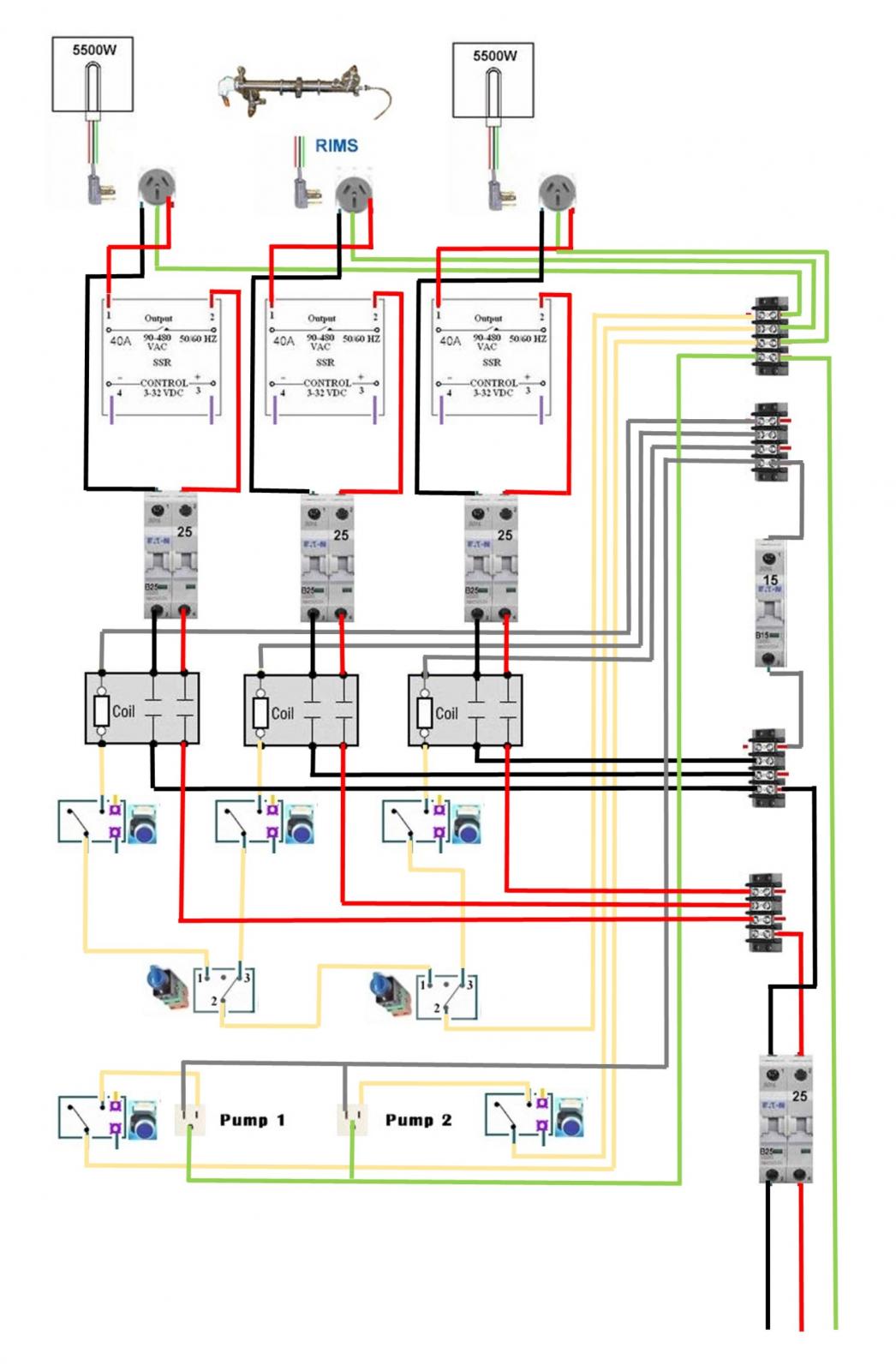
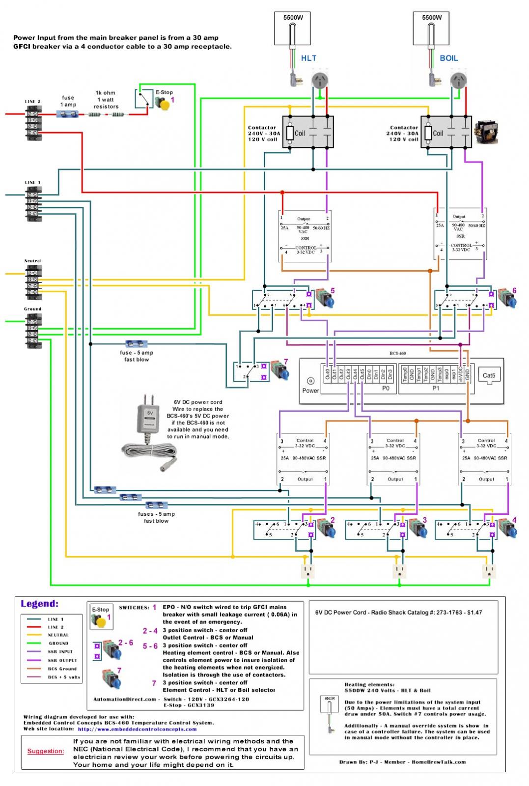
List of PJ Electrical Diagrams

Homebrew Talk

Help Support Homebrew Talk:

This site may earn a commission from merchant affiliate links, including eBay, Amazon, and others.
Whoa! I didn't Mean to quote all of them. But that second one is what I am looking for. Thank you my friend!

You are welcome. The second one was edited from the third from the bottom in your post. I should have put a notation in the drawing that it was edited from PJ's original. I needed to work on my GIMP foo.

Edit: Added note to second diagram in previous post that it was modified from PJ's original.

Brew on :mug:
 
Roger that. It is exactly what I am looking for. Are those SSR's between the PID and switch? Sorry if it's a basic question. I just want to make sure I wore everything right!
 
Roger that. It is exactly what I am looking for. Are those SSR's between the PID and switch? Sorry if it's a basic question. I just want to make sure I wore everything right!

Yes, those are SSR's. Instead of just blocks, P-J used block diagrams of SSR's that show the internal circuitry of an SSR.

Brew on :mug:
 
Yes, those are SSR's. Instead of just blocks, P-J used block diagrams of SSR's that show the internal circuitry of an SSR.


Brew on :mug:


I just ordered everything for the panel! What size wire, for which, would you suggest.

I can't wait to get this build going! Still waiting on the Kettles from Colorado Brewing Supply. But everything else is lining up!
 
First, I would like to thank P-J and all the others for all their hard work.
I finally finished reading this entire thread and have a question to ask before my brain trips its GFCI...

I'm planning on building a RIMS with two pumps, one PID (SYL-2352), with 1500W or less element (120V) and fancy illuminated switches.
Hey, I'm a retired Air Traffic Controller, and after spending the better part of my adult life in a dark room without any windows, I've grown accustomed to fancy illuminated switches.

Anyway, I like P-J's "Auberin-wiring1-SYL-2352-basic3a-RIMS" diagram. I believe that was the one he made for SweetCell.

In the diagram the R30A mini relay has the coil wired to the "heat" switch and RIMS element (left side of relay).
The right side is wired to the RIMS element and the SSR.

Looking at the photo of the R30A relay, the connections on the right are COMM, NO and NC.

Is the RIMS and SSR wires connected to "N Open" or "N Closed" position along with the COM position?

P-J, hang in there. I may not be as old as you but I'm pretty close behind.
So don't make any sudden stops.

Any help is greatly appreciated.
I'm not fast anymore...I'm now half-fast!


Mini Relay R30A small.jpg


Auber R30A mini relay
Auber R30A Mini Relay.jpg
 
First, I would like to thank P-J and all the others for all their hard work.
I finally finished reading this entire thread and have a question to ask before my brain trips its GFCI...

I'm planning on building a RIMS with two pumps, one PID (SYL-2352), with 1500W or less element (120V) and fancy illuminated switches.
Hey, I'm a retired Air Traffic Controller, and after spending the better part of my adult life in a dark room without any windows, I've grown accustomed to fancy illuminated switches.

Anyway, I like P-J's "Auberin-wiring1-SYL-2352-basic3a-RIMS" diagram. I believe that was the one he made for SweetCell.

In the diagram the R30A mini relay has the coil wired to the "heat" switch and RIMS element (left side of relay).
The right side is wired to the RIMS element and the SSR.

Looking at the photo of the R30A relay, the connections on the right are COMM, NO and NC.

Is the RIMS and SSR wires connected to "N Open" or "N Closed" position along with the COM position?

P-J, hang in there. I may not be as old as you but I'm pretty close behind.
So don't make any sudden stops.

Any help is greatly appreciated.
I'm not fast anymore...I'm now half-fast!


View attachment 290051


Auber R30A mini relay
View attachment 290052
You would use the NO contact on the relay (and the switch controlling the relay coil as well.) You want the relay open (no power to the element) until the switch energizes the coil.

Brew on :mug:
 
doug293cz, et al

Thanks for your quick reply.
I have another question.

In "P-J's" diagrams he uses the Auber SW1 switch.
I'm considering using the SW16 switch.

Is the wiring for the SW1 any different than the SW16?

Thanks in advance
 
doug293cz, et al

Thanks for your quick reply.
I have another question.

In "P-J's" diagrams he uses the Auber SW1 switch.
I'm considering using the SW16 switch.

Is the wiring for the SW1 any different than the SW16?

Thanks in advance
Looks like the SW16 can be easily substituted for the SW1. Contacts appear to be in similar locations.

Brew on :mug:
 
Hey Guys -

I got this 25' inline gfci cable TRC-44720-020 that's 240V, 30A, 10/3 for $143 shipped. After doing more research, apparently there's a TRC-24140-002 that's around $130 shipped off of ebay (new - there are some ones that look used for $80), but then 25' ft of cable would be around another 30.

My dryer is a 4 wire outlet - is there any benefit in trying to return the 10/3 inline one and getting the 10/4 one? I'm planning on running a single 4000w or 5500w element in a kettle. Right now some buddy's are scaring me about burning down my condo with a 5500w element so I might go lower. The reason I'm not doing a spa panel is there's barely any room near my washer/dryer (stacked unit with like 4" of play).

Also - any input on my rough schematic (based off a few from the OP)? It'll be either a 240V or 2x120V setup:

schematic.PNG

Thanks!
 
Hey, I saw this circuit diagram on one of the front pages of this thread and was wondering if P-J or someone had done it for a 15A breaker? If not could someone alter it?

I am assuming that would need a 1500W 120V element or lower? And would change the fuse from 20A to 15A?

If anyone could recommend an element as well would be great. I plan to have this exact setup, but need it to be altered to 15A.

Auberin-wiring1-SYL-2352-basic5-RIMS.jpg
 
You could use a 240v 5500 watt element. That would put out 1375 at 120v, putting you well within your 15 amp circuit. It would also be incredibly low watt density which is always nice
 
Hi P-J or any one that knows, what software are you designing these schematics in, I'm doing the same thing in publisher and drawing a strait line or snapping to another is close to impossible

Look into Inkscape (https://inkscape.org/en/). It is a free vector graphics program that runs on Windows, OS X and Linux. It has a variety of "snap" modes.

Brew on :mug:
 
smart draw works pretty good too, I can lay out a box in 30 minutes but took me 4 hours to draw these freaking lines and keep them strait
this is my 3 wire set up drawn from a perspective of roughly laid out in the box, this is in publisher 2013

one is simplified by joining wires and the other is full wires, one wire to each device, same layout

Power wiring - simplified.jpg


Full_Wiring_Power_grid.jpg
 
You could use a 240v 5500 watt element. That would put out 1375 at 120v, putting you well within your 15 amp circuit. It would also be incredibly low watt density which is always nice

What would be the advantage of this over 120v 1500 watt, and how would it change the diagram I linked in my original post?
 
What would be the advantage of this over 120v 1500 watt, and how would it change the diagram I linked in my original post?

Advantage - Already have the element if you opt to go 240v in the future. Much lower watt-density than the 1500w, so more gentle heating and less chance of any scorching.

Disadvantage - It's a bigger element so you need to factor that in. It only puts out 1375 vs 1500w so slightly less power.

Change to your diagram - zilch.
-Kevin
 
I just ordered a 20 gal Colorado brew system BIAB kettle.
I want to use a BCS 460 controller. Can I use this and simply not add the other two elements?
I just have one element and one pump.
Yes I know its overkill, but I like the format and want it in case I decide to go back to 3V brewing.

If anyone has a similar set up I would be much appreciated for tips.

I have already run the 6/3 wire to the 50A Spa Panel w GFI.

Kenneth-BCS-460-wiring-2-4a.jpg
 
I just ordered a 20 gal Colorado brew system BIAB kettle.
I want to use a BCS 460 controller. Can I use this and simply not add the other two elements?
I just have one element and one pump.
Yes I know its overkill, but I like the format and want it in case I decide to go back to 3V brewing.

If anyone has a similar set up I would be much appreciated for tips.

I have already run the 6/3 wire to the 50A Spa Panel w GFI.

That's way too complex a diagram to start with for a single element, single pump system. You should start with something more like this:

Single elem single pump schem.jpg

Personally, I would put the red hot leg thru the contactor before the SSR, rather than after as shown, but either will work.

Brew on :mug:
 
Yes...thats what i am looking for. Is there any reason the PID BCS cant be interchangeable?


[

QUOTE=doug293cz;7089457]That's way too complex a diagram to start with for a single element, single pump system. You should start with something more like this:

View attachment 302197

Personally, I would put the red hot leg thru the contactor before the SSR, rather than after as shown, but either will work.

Brew on :mug:[/QUOTE]
 
Yes...thats what i am looking for. Is there any reason the PID BCS cant be interchangeable?

You can swap the PID for any controller with a digital output within the voltage range of the SSR input.

Brew on :mug:
 
yes...thats what i am looking for. Is there any reason the pid bcs cant be interchangeable?

What are the blue circles on the for?
[

quote=doug293cz;7089457]that's way too complex a diagram to start with for a single element, single pump system. You should start with something more like this:

View attachment 302197

personally, i would put the red hot leg thru the contactor before the ssr, rather than after as shown, but either will work.

Brew on :mug:
[/quote]
 
Hey Guys -

I got this 25' inline gfci cable TRC-44720-020 that's 240V, 30A, 10/3 for $143 shipped. After doing more research, apparently there's a TRC-24140-002 that's around $130 shipped off of ebay (new - there are some ones that look used for $80), but then 25' ft of cable would be around another 30.

My dryer is a 4 wire outlet - is there any benefit in trying to return the 10/3 inline one and getting the 10/4 one? I'm planning on running a single 4000w or 5500w element in a kettle. Right now some buddy's are scaring me about burning down my condo with a 5500w element so I might go lower. The reason I'm not doing a spa panel is there's barely any room near my washer/dryer (stacked unit with like 4" of play).

Also - any input on my rough schematic (based off a few from the OP)? It'll be either a 240V or 2x120V setup:

View attachment 296337

Thanks!

Any inputs?
 
Any inputs?

the second option has a 10 ma trip level for the gfci, which does not meet the requirement of a class a device (trip at 4-6 ma). 4-6 ma trip levels are the levels you see in gfci receptacles in bathrooms, etc. and are the trip levels designated for 'personnel protection'. so the second option would 'work' but if you were caught in a weak ground fault of, say, 9 ma, the gfci device may not operate. at 9 ma, it may be difficult to let go of the energized item you are in contact i.e. you'll sit there getting shocked and can't let go.
 
Gotcha - I went with the 3 wire 240V inline gfci... I was hoping for feedback on the attachment (see below).. after I got the connectors, a buddy said why not redo it so that you only need 2 power inputs instead of 3.

schematic.PNG
 
Back
Top