Doug293cz,
I'm happy to say "That makes sense!!"
I was planning on keeping all of the electrons for each circuit separate in the control box, especially since only one of the circuits will be multipurposed - the 120V/20A circuit that powers up the BCS-462, pumps, valves, AC/DC transformers and the relay boards. The other three circuits are dedicated to running their respective hot water heater elements (HLT, BK, RIMS), so the electronics on those circuits should be simple. The only place where these four circuits will technically "meet" is at the BCS-462, since it will control the SSR/Contactors that drive everything. The "brain" sits electrically behind the SSRs and Contactors, which physically separate the electrons in the other circuits.
Am I getting it, or am I overlooknig something?
Thanks!
Namako
")
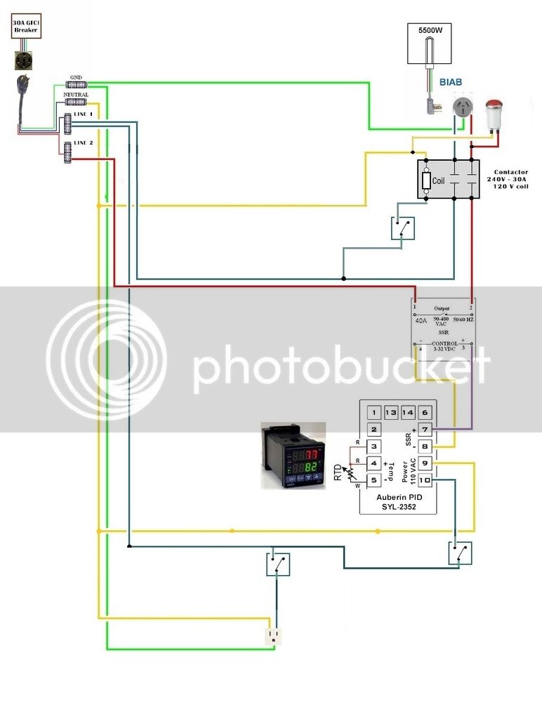
I think you've got the idea. I put together a little schematic for the power input switching that should do what you want to do (if anyone sees any issues, please let me know.)
- Neither of the 240V neutrals make any connections inside the control box
- The neutral for the RIMS heater connects only to the RIMS heater, and nothing else
- A common neutral is used for all pumps and control circuits
- The RIMS power switch must be rated for the full RIMS current, or else replaced by another contactor + switch
- The Main Power switch and EPO can be low current
- The EPO switch must latch in position when pressed
- The SSR control inputs are optically isolated from the power side, so no worries about what connects to them
Brew on


![Craft A Brew - Safale BE-256 Yeast - Fermentis - Belgian Ale Dry Yeast - For Belgian & Strong Ales - Ingredients for Home Brewing - Beer Making Supplies - [3 Pack]](https://m.media-amazon.com/images/I/51bcKEwQmWL._SL500_.jpg)