kpr121
Well-Known Member
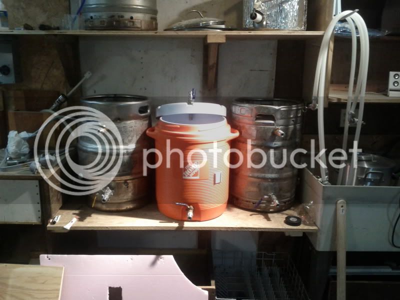
Oh and here is where we are for the weekend, American side


TrainSafe said:That is freaking gorgeous! Nature's beauty is impressive.
It is quite amazing to think that much water is ALWAYS flowing over the falls!


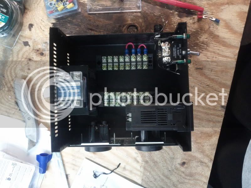
Where did you get your terminal strips/bus bars? I found some at radio shack that are rated for 15 amps at 1100vrms. But not sure how that translates. They also carry neat 8 position jumpers that eliminate the need to make a bunch of jumpers by hand. I found heavier duty terminal strips at local home improvement stores but they are easily twice the cost.
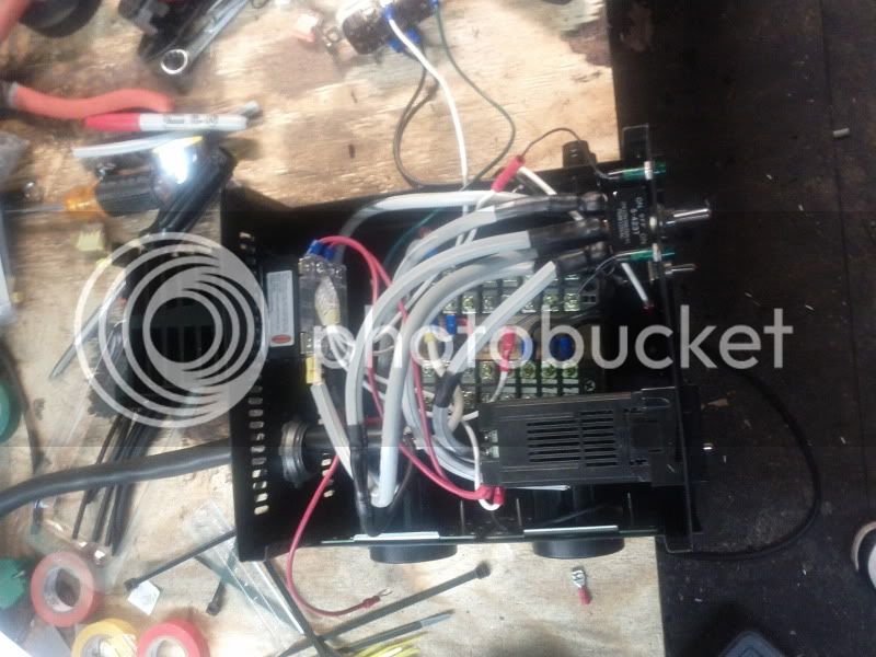
omockler said:Those push in connectors look nice. Are you thinking about putting a cooling fan in your control box?
It looks like you have the same ssr and heat sink that I have and that thing gets seriously hot when it is running full blast.
The stuff I used seems to stay pretty gooey so I don't think it would be too hard to pull the heat sink off the ssr but I'm not sure all thermal compounds are the same.
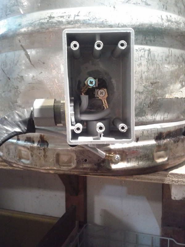
Junction box wired up. Used some electric tape wrapping (yea very professional) to keep the ground wire close to the other two to minimize snagging. Waterproof faceplate goes on front.
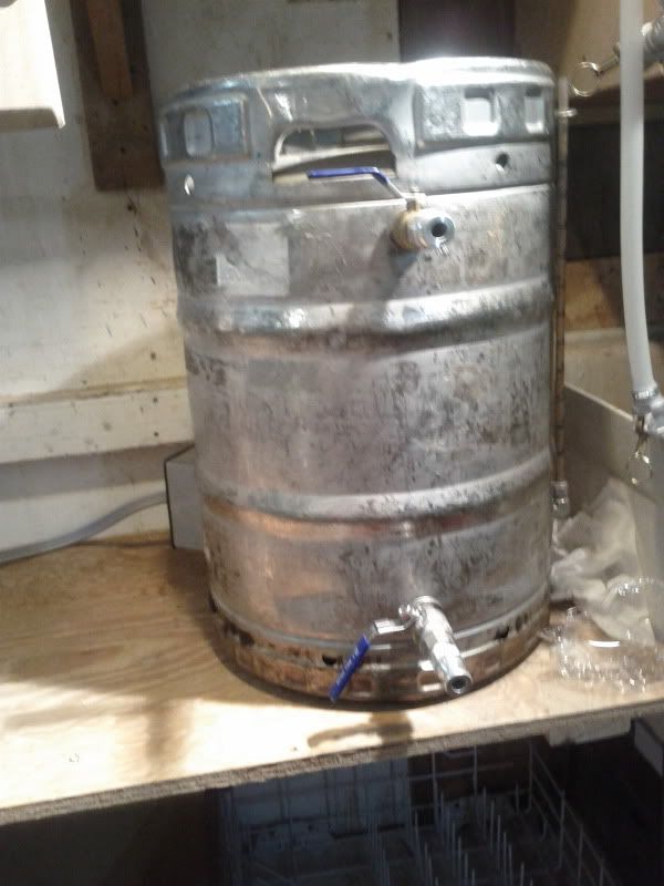
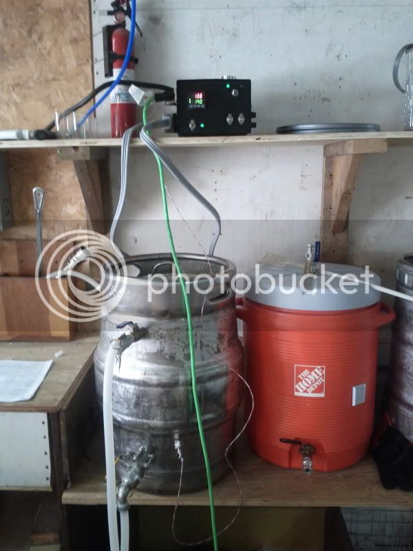
Here's what the BK looks like in place. Notice the junction box out of the way towards the back.
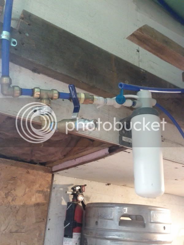
Here's my plumbing job of the non filtered bypass.
I would be VERY careful when using this for the first time. I assume that is a BK and you plan on boiling with it (212F). Those carlon boxes have a max operating temp if less than 180F. Personally I would replace it with a metal gang box.
During HLT use my metal gang box still gets hot enough to be uncomfortable to touch (and I have kitchen hands from years of chefdom working my way through college)
P-J: I have a question regarding the stepped-down breaker protection within the control panel. If you or a mod feels this is off topic to this thread, please feel free to answer in my build thread (see sig link below).
If I have a 40 amp circuit, would I need to run all 8 gauge wire in the control panel (other than fused runs such as PID/Pumps/E-Stop) if I wanted to avoid putting in separate circuit protection?
And will I be okay if my connections (switches, terminal blocks, etc.) are not rated to 40 amps?
I feel like the answer to the second question is no, and that I should just put in separate protection for this reason as well as ease of wiring, but I just wanted to get your thoughts on 40 amp service since everyone is usually using either 30A or 50A.
What fuses/circuit breakers do you recommend for installing in the control panel? If this is too much of a pain, I may just replace the main breaker with a 30 amp one and be done with it. I didn’t want to limit the amperage since I got a good deal on 6 gauge (albeit aluminum) wiring from the breaker to the garage.
kpr121
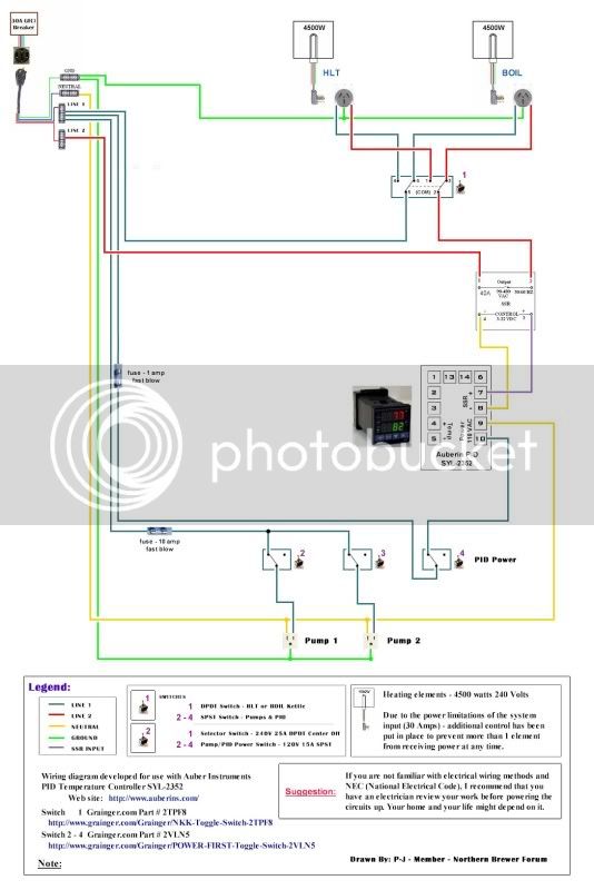
With a 30A 240V feed, the elements would normally be powered with a 30A circuit. I also illustrate seperate fusing for the low power 120V devices within the controller. For a 40A or 50A feed you must provide circuit protection within your controller. Fuses for 120V devices are A-Ok. IMHO, the 240V devices must be protected with circuit breakers so that both of the 240V lines are interupted together. It is not just about protecting the wire. It is also very much about protecting the devices involved and you.
Automation Direct is a source for 25A - 240V DIN breakers: Double_Pole - WMZS2B25
And 15A - 120V DIN breakers: Single_Pole - WMZS1B15
Here are the rails: Rails - DN-R35S1-2
Hope this makes sense.
It may be totally fine, or just work for several months then denature, crack, etc. I do know I read a spec sheet calling out 173F for a max temp. and didn't want to see you, or anyone else get hurt.
A lot of guys are considering and starting to use plastic gang boxes/enclosures; the price point is not that different to warrant the safety risk IMO. Just my .02
I am not sure on the PVC rating, but I think it is higher.
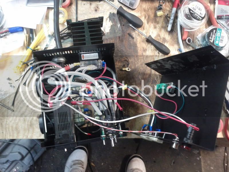

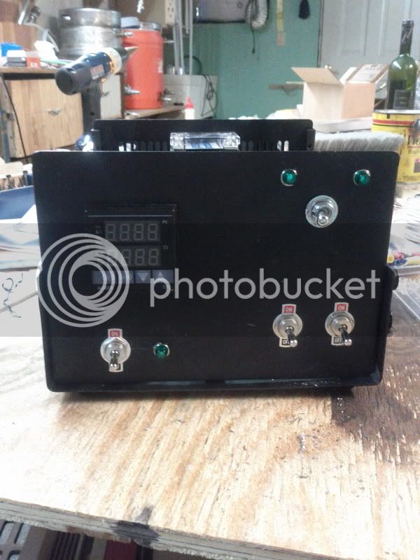
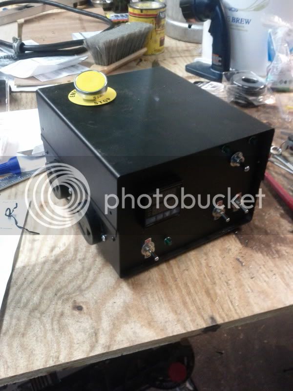
dan6310 said:Congrats man! The hard part is done.
Your right, no room for expansion in there. Keep an eye on potential heat build up with it being packed. Hopfully the ventilation in the rear will be enough.
Dan


 ). Picked up the Mash Recirculation Return Tube, a refractometer, decals for both sight glasses, and also custom decals for the control panel!


