It can't be this difficult!

Homebrew Talk - Beer, Wine, Mead, & Cider Brewing Discussion Forum

Help Support Homebrew Talk - Beer, Wine, Mead, & Cider Brewing Discussion Forum:

This site may earn a commission from merchant affiliate links, including eBay, Amazon, and others.

Vintage Iron

Well-Known Member
Joined
Jan 2, 2018
Messages
117
Reaction score
33
Location
St. Croix River Valley in Western Wisconsin
Currently trying (unsuccessfully) to find a plug and play 220V controller for an electric element in a boil kettle. (have a Spike 15gal kettle with tri-clover fittings near the base.) I picture something like a Auber controller with the rotary dial.

Does anybody make a pre-built controller for this set up? This is only for the boil phase as I already have Inkbird IPB-16 (110V) that runs a RIMS tube during the mash.

There doesn't need to be any automation with this, I'm simply looking to control the electric "flame" like you would with a propane burner.

Thanks!
 
Thanks for all of the info so far. I really like that Still Monkey kit. Didn't realize it could be that simple! The more I research and learn about how these controllers work, I'm starting to come up with a build plan, please tell me what you think.

My 220V outlet is not GFCI, so my thought is to buy a spa panel from Home Depot and also use that box as the enclosure for the boil controller. There would be a short cord with a plug coming out of the spa panel to to into the 220v outlet, and another cord with a receptacle on it for the actual heating element. If one wanted to step up a bit from the Still Monkey kit, would it work to replace the simple dial they have with one of these?

https://www.auberins.com/index.php?main_page=product_info&cPath=53&products_id=444

Then that's all I'd need would be the SSR, and heat sink, correct?

Thanks again for all of the help!
 
Thanks for all of the info so far. I really like that Still Monkey kit. Didn't realize it could be that simple! The more I research and learn about how these controllers work, I'm starting to come up with a build plan, please tell me what you think.

My 220V outlet is not GFCI, so my thought is to buy a spa panel from Home Depot and also use that box as the enclosure for the boil controller. There would be a short cord with a plug coming out of the spa panel to to into the 220v outlet, and another cord with a receptacle on it for the actual heating element.

Why not just replace the breaker for the outlet with a GFCI breaker? Spa panels include a 50 amp GFCI breaker, and they tend to be a little less expensive than buying the breaker by itself (I'll never figure that one out...) but you have to build the spa panel and buy extra cords, plugs, and receptacles. I think it's cleaner to just replace the supply breaker.

https://www.homedepot.com/p/Square-...ole-GFCI-Circuit-Breaker-HOM230GFIC/204355352

Most homes use the Homeline style breakers, but you can find other versions if you have a different type of breaker panel.

I also wouldn't reccomend trying to put the Still Dragon controller into a Spa Panel. They usually don't have much room inside them, and that SSR heatsink looks like it will take up a lot of room.

If one wanted to step up a bit from the Still Monkey kit, would it work to replace the simple dial they have with one of these?

https://www.auberins.com/index.php?main_page=product_info&cPath=53&products_id=444

Then that's all I'd need would be the SSR, and heat sink, correct?

Thanks again for all of the help!

The Still Dragon controller comes with a heat sink, and all these SSR's are a standard footprint, so you'd be able to reuse that. It looks like the SSR that Still Dragon provides has the potentiometer directly wired to it, which means it's not compatible with Auber's controller, so you'd need a different SSR to work with Auber's controller. The hardest part of that would be building a box to hold the auber controller, and all the Still Dragon components but they sell those too: https://www.auberins.com/index.php?main_page=product_info&cPath=34&products_id=143

Just make sure the box is big enough to hold everything you want - you run out of space inside those boxes really quick! Electrical controls enclosures are like garages: You can never have too much space.
 
Last edited:
My 220V outlet is not GFCI, so my thought is to buy a spa panel from Home Depot and also use that box as the enclosure for the boil controller.

Nothing wrong with a spa panel, but you could also change out the circuit breaker that controls the 220V outlet in your main service panel.

Looks like the SSR is replaced by a rheostat in the Still Dragon kit, which is kind of what I looked into first. I do like the price on that.

I went with the Auber cube, and do not use all of its automated options. Maybe some day I will, it works well for what I use it for, but it might be easier to use at first if it did not have so much automated options.

One good thing about a little automation is in mash mode with EZ Boil (the control unit in the "Cube") you can set desired strike, sparge or sanitation water temp and walk not have to hover over it to make sure you do not overshoot. This is especially useful on the strike water temp, makes it easier to hit mash temp target first time.
 
There are a ton of standalone prebuilt controllers that you could use for your setup, the following come to mind of the top of my head.

High Gravity - 2 people in my club this for E-HERMS
Hosehead - 1 E-BIAB, 1 Two Vessel, 1 E-HERMS users in my club
EBrewSupply - 1 E-HERMS users in my club
BrauSupply
Clawhammer
Grounded Brewing

If you JUST want boil control, I'd recommend https://www.highgravitybrew.com/store/pc/Brewery-Controller-Electric-Kettle-272p3084.htm

I had to use a spa panel because my breaker box only had 3 wires, its pretty easy to wire one and you should only need about 4 ft total of wire and a terminal to make it work.
 
Last edited:
If you can do a 4-wire installation, you should do that. 3-wire is the old standard.

I agree, putting in a GFCI breaker in your breaker box may be the best idea. There are several different manufacturers of such boxes, you have to be sure you get the right one. Square-D makes two different styles, there's Siemens, Eaton...some others that are less common. Take a picture of your breakers and box before you go the hardware or home store to look for the breaker.

Price varies; I have a non-homeline Square-D box, and a 30-amp GFCI breaker for that cost $103. Yeah. Others are around half that.

Even if that's the breaker you need, compare that with getting a spa panel, the wiring for it, etc. I looked at a SPA panel and realized it would limit what I could do, so that disappeared from the plan.

********

Finally--some of this depends on the local circumstances, where you can or cannot run wire, and so on. I decided to run a 60-amp line out to my garage (6 ga), put in a sub-panel, and used that to house the 30-amp GFCI as well as a couple of additional 20-amp circuits. If you have long-term designs on really amping up your brew space, consider how you'll allow for future expansion.

I have the 30-amp GFCI feeding my control panel; one of the extra 20-amp circuits runs my RIMS controller and element (120-v), and the other is for my glycol chiller.

All I'm saying is if you think you might further expand in the future, leave room to do just that.

Good luck!
 
But it is this difficult :)
Not really, but there are a lot of choices (see above, right?)
You might want to consider how quickly you want to start and current funds available:
I started with a spa panel and still dragon type set up plugged into the dryer outlet, all for about $100 at the time. Now have a 50 amp GFCI breaker running a dedicated 'brew circuit' in the garage and a home-made panel with all kinds of goodies. I was able to re-purpose some of my old set up (got lucky that the spa panel breaker fit in my house circuit panel) and either sold or gave away parts I could no longer use to fellow brewers.
 
Remeber though, breakers need to match the box's brand. So even though the one you linked work for you, it wont work for others.
 
OK, good news. I went ahead and picked up and installed a 50Amp GFCI breaker. (This circuit is used for a welder as well, hence the 50amps)

IMG_1239.jpeg

Now it's time to build the controller. If we have any resident electric geeks, could you please critique the parts list?: (Keep in mind, this is just for boiling)

55W Element: https://www.brewhardware.com/product_p/element5500_ripple_tc.htm

Power Regulator: https://www.auberins.com/index.php?main_page=product_info&cPath=53&products_id=444

40A SSR: http://www.auberins.com/index.php?main_page=product_info&cPath=2_30&products_id=30

Heat Sink: https://www.auberins.com/index.php?main_page=product_info&cPath=2_48&products_id=224

Obviously I'll need some thermal grease, wire, and a 50A plug to get power in, and a 30amp female recepticle to get power out to the element. Any thoughts are greatly appreciated.
 
OK, good news. I went ahead and picked up and installed a 50Amp GFCI breaker. (This circuit is used for a welder as well, hence the 50amps)

View attachment 598914

Now it's time to build the controller. If we have any resident electric geeks, could you please critique the parts list?: (Keep in mind, this is just for boiling)

55W Element: https://www.brewhardware.com/product_p/element5500_ripple_tc.htm

Power Regulator: https://www.auberins.com/index.php?main_page=product_info&cPath=53&products_id=444

40A SSR: http://www.auberins.com/index.php?main_page=product_info&cPath=2_30&products_id=30

Heat Sink: https://www.auberins.com/index.php?main_page=product_info&cPath=2_48&products_id=224

Obviously I'll need some thermal grease, wire, and a 50A plug to get power in, and a 30amp female recepticle to get power out to the element. Any thoughts are greatly appreciated.
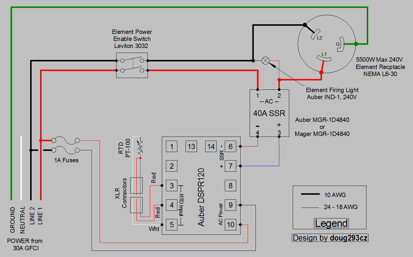
You should also include some type of mechanical positive disconnect switch - DPST. Either a high current direct acting switch (like a Leviton 3032) or a low current switch plus contactor. SSR's tend to fail in the "on" state, and also they only switch current, leaving enough voltage to give you a good shock even when "off." Another good addition is a 240V LED indicator lamp in parallel with the element. This light will tell you if the SSR is actually switching as commanded by the controller, or if it has latched on or failed entirely. Here's about the simplest control arrangement I would recommend:

DSPR120 1-Element  240V only.PNG


The DSPR1 has different terminal assignments than the DSPR120 shown, and does not have the PT-100 temperature probe, but otherwise this diagram will do what you want.

Brew on :mug:
 
Thanks Doug!

Your ideas about a switch and a light certainly make sense.

One question about your diagram. On the "power from 30A GFCI", would I be substituting the (white) neutral wire for where you have the (green) "ground" wire headed to the element receptacle if my set up is a 3-wire set up rather than a 4 wire?
A three wire outlet has a ground, and no neutral. What are the colors of the wires connected to your outlet?

If you don't like the aesthetics of the Leviton 3032 switch (looks like a wall light switch), I can give you some other options.

Brew on :mug:
 
Doug-
The wires connected to my outlet are Red, Black, and White. You can see them in the pic of the sub-panel box (posted earlier this evening) if you like a visual. Sorry, my terminology make be incorrect between "ground" and "neutral".

Yes, if you have other 220/240V switch options (and don't mind taking the time) I'd certainly be open to considering other options.

Thanks again
 
Ok, you actually have four wires leading out of the sub-panel. The red and black are hots, the white is neutral, and the bare wire is ground. Your three slot outlet should not have the white connected. If you used the white wire as a ground, then your GFCI breaker would not work correctly.

Brew on :mug:
 
Doug-
I REALLY appreciate your help, so please keep at it.

Here is a pic of the instruction sheet that came in the GFCI breaker box:
(The wire marked "D" is the neutral, and the "E" wires are the load power wires, so I think that is hooked up correctly?)

IMG_1250.jpeg

Here is a pic of my (50amp) outlet.

IMG_1249.jpeg

I pulled the cover and removed the outlet from the box so I could confirm the wire routing just to be sure. The bare copper ground wire is lugged off onto the inside of the metal junction box behind the outlet. The two load wires are going to the parallel spades on either side, and the white neutral wire is going to the single terminal at the top of the outlet. Again, from everything I'm reading online, it appears as though most hot tubs are wired with 3 wires in this arrangement with the ground not being actively used, so I'm about 95% sure that this is correct, but if you have some thoughts on this, I'd love to hear it. (Again, I appreciate your help as I'd rather not fry my arse should something go wrong.)
 
That outlet as configured is NOT protected by the GFCI and is not up to code. You need a Ground for the breaker to detect a Ground Fault. The proper way to hook up a 3-wire 240v outlet is Hot/Hot/Ground, which will typically be Black/Red/Green (or bare).

The good news is you're probably going to be replacing this outlet anyway, as if your panel is going to support 120v pumps it's going to have a 4-wire input. In a 240v system, Neutral is only used to support 120v loads. For straight 240v, Neutral is not required. Look at the element outlet on your diagram above--2 hots and a ground, no neutral. With this 50A outlet as wired, the only way to accomplish this is to independently bond your panel to the ground bus in your spa panel.

Here's a wiring diagram of several common outlet types. Your current one is the 6-50R:

Figure-2-620x329.jpg


You will likely be replacing this with a 14-50R to support your panel. But notice how the only two outlets that even have a neutral are the 120V and the 4-wire 240v.

Can you share with us the resources where you found this wiring setup to be common for hot tubs? Because as-configured a leak could kill everyone in it. It was most likely set up for a VERY old (before grounded outlets were code) 120/240v dryer
 
LAX-
Thanks for the reply. You guys are amazing. Here is a not-cropped down version of the install instructions. As you can see on the left side of this diagram, it shows the routing of the neutral wire, the two "load" wires, and then the curly wire going to the neutral bar in the box.

IMG_1250.jpeg

It sounds like we all agree on that part, but it's the connection at the outlet end of the set up that I'm off. After further research, it looks like you are correct, and I was confused.

I just figured out where my confusion was happening. Here is an example of some info I was looking at. It's a YouTube video of a guy describing the hook up. I see now that it looks like the common and the ground need to be bridged inside the box on these three wire hook ups. If you fast forward to approx 4:34 in the video, you'll see him describe this. It sounds like if I tie those two together, life should be happy. Correct?

Here's the link


I will not be replacing this outlet as it is primarily used to run a welder. I do understand (with this 3 wire set up and the neutral and grounds tied together in the box) that I cannot pull 110V off of this, and that's fine. We have a separate 110V circuit that I'll be using to power the pump. This 220v GFCI circuit will only be used for a boil pot (or the welder as previously mentioned)

Thanks for your help and patience with me.
 
I see now that it looks like the common and the ground need to be bridged inside the box on these three wire hook ups. If you fast forward to approx 4:34 in the video, you'll see him describe this. It sounds like if I tie those two together, life should be happy. Correct?

The situation he's describing is where only three wires are coming into the spa panel. You have four. Ground and neutral should be bridged in every electrical system in one and only one place--nearly always the main panel. Bridging them again elsewhere in the system provides an alternate path to ground via the neutral bus, which you do not want. A well-designed electrical system requires two faults before risking electrocution. By bridging the ground and neutral, you would be intentionally introducing one of those faults. In effect, this is what you have now, because the ground and neutral wires are mechanically connected at the outlet by virtue of the mounting tabs contacting the box.

If you're not replacing the outlet, just cap the neutral wire and move the ground wire from the box to the ground lug on the outlet. You will then have a code-compliant Hot/Hot/Ground 240v outlet, and your GFI will work.

There's some great background information in this discussion of 3-wire setups: https://www.homebrewtalk.com/forum/threads/3-wire-240-outlet-to-spa-panel-wiring-question.506074/
 
Last edited:
Wow... You guys are amazing!

I certainly see what you're saying about doubling up on the bridging of the ground and neutral. That makes sense since this outlet it connected to a sub-panel in the garage and not the main panel in the house. So, should just disconnect the white wire coming OUT of the GFCI breaker then since it won't be used at the outlet end and cap off both ends?

So, one last question. In the thread you referenced, they mention this:

ground wire.jpg


This is the main reason I am reluctant to use the bare ground in the outlet. Should this be a concern? Obviously burning the house down is not an option at this point. LOL

Obviously this entire situation would be rectified by running new (4 conductor) wire and using a 4-prong outlet, but I'm trying to make this work (safely) without ripping out drywall and creating the need for a rewire of the welder as well.

Thanks again for helping me make this as safe of a set up as possible!
 
I certainly see what you're saying about doubling up on the bridging of the ground and neutral. That makes sense since this outlet it connected to a sub-panel in the garage and not the main panel in the house.

Ack! This means it has never been to code. There used to be an exemption that allowed this, provided the outlet was directly attached to the service entrance (main panel) where the neutral and ground are bonded. See this from the thread I linked:

Those HHN circuits were only allowed when wired directly to the main service panel. That's why mobile homes have always used 4-wire outlets for dryers; their main service disconnect is out on the pole. So the 3rd wire is connected to BOTH the ground bar and the neutral bar because they are both tied together in the breaker box. (this assumes it was installed correctly) You can safely use it for a neutral connection OR a ground -- but you shouldn't use it for both (actual electric dryers exempted.)

So, should just disconnect the white wire coming OUT of the GFCI breaker then since it won't be used at the outlet end and cap off both ends?

Yes. To be clear, by "coming out" I mean the lug that's in between the two hots on the breaker itself. The pigtail MUST be connected to the neutral bus in the box (which in turn must be connected all the way back through the subpanel to the neutral bus in the main panel) in order for the GFI to function.

So, one last question. In the thread you referenced, they mention this:

View attachment 599147

This is the main reason I am reluctant to use the bare ground in the outlet. Should this be a concern? Obviously burning the house down is not an option at this point. LOL

Obviously this entire situation would be rectified by running new (4 conductor) wire and using a 4-prong outlet, but I'm trying to make this work (safely) without ripping out drywall and creating the need for a rewire of the welder as well.

Thanks again for helping me make this as safe of a set up as possible!

The warning there is not to use an uninsulated ground wire as a neutral. And that is correct, because neutral wires are expected to carry return current in a 120V circuit. Ground wires inside structures are generally not insulated (they have to be for exterior wiring, for a different reason). This is because contact between the ground wire and boxes/conduit/etc is not undesirable, and in many cases is explicitly required by code. So there is no need to insulate it, because everything it should NOT touch is insulated.

Make no mistake, you are using the bare ground wire now, because the ground lug on the outlet is bridged to the mounting "wings" on the outlet, which are touching the metal box, which is grounded using that wire. By moving it, you are just making a more secure, direct ground connection. Unless there's an actual problem with the existing wire somewhere, replacing it with a new 4-conductor cable with insulated ground will not increase safety in any way.

The reason you need an insulated ground wire in exterior wiring is not to prevent it from touching other things in the wiring run, but to prevent corrosion from decaying the wire and causing a loss of ground.
 
Here's what I did today. First, disconnected the neutral wire from the center lug of the GFCI breaker and capped it off with a wire nut.

IMG_1262.jpg

Next I pulled the outlet, disconnected the neutral and capped it off for good measure, then ran the bare ground wire to the top terminal of the plug.

IMG_1263.jpg

All good now? Thanks again for all of the help!
 
Here's what I did today. First, disconnected the neutral wire from the center lug of the GFCI breaker and capped it off with a wire nut.

View attachment 599210

Next I pulled the outlet, disconnected the neutral and capped it off for good measure, then ran the bare ground wire to the top terminal of the plug.

View attachment 599215

All good now? Thanks again for all of the help!
Yep, good to go.

Brew on :mug:
 
Back
Top