Is this even possible? EBIAB dual 120/240v controller

Homebrew Talk - Beer, Wine, Mead, & Cider Brewing Discussion Forum

Help Support Homebrew Talk - Beer, Wine, Mead, & Cider Brewing Discussion Forum:

This site may earn a commission from merchant affiliate links, including eBay, Amazon, and others.

singybrue

Well-Known Member
Joined
Oct 26, 2013
Messages
596
Reaction score
224
Location
Minneapolis
I would like to build one controller that can do both small batches using a 120v 2000w element or larger batches using a 240v 5500w element.
I would have a small pot with a 120v element installed and a big pot with a 240v element installed. My hope would be to use a switch to select 120 or 240v. It would have separate wiring and receptacles for the different elements.
I would like to use this new Auber EZ Boil controller-http://www.auberins.com/index.php?main_page=product_info&products_id=560
I would also like to incorporate this timer-http://www.auberins.com/index.php?main_page=product_info&products_id=562
as well as a switch controlled 120v pump receptacle.
Is this possible? Anyone want to draw it up for me?

Yes, it is very possible. I can take a stab at drawing this up. Although I may leave the timer out, but connecting it is trivial.

Edit: Just noticed the timer you linked is 24V power supply. This will complicate the design. I recommend you use this timer instead. Same functionality, but powered by line voltage.

Brew on :mug:

Thanks Doug! I would really appreciate it! I didn't notice the timer was 24v-I don't want that. The standard voltage timer is want I want.
If you need any more info from me, let me know. I'll probably be buying most of the parts from Auber.
I'm glad you found this post, as I screwed up and put it in Equipment, instead of Electric Brewing like I intended.
 
Ok, take a look at this design. I think it covers all of your requirements. My drawing program doesn't have a large enough selection of line widths, so I used the same width line to represent 12 AWG and 16 AWG wiring. Everything downstream of the 10A fuse can use 16 AWG, and the 120V element wiring requires 12 AVG. Of course, you can always use heavier wire than required for the amperage, but finer wire is easier to work with. Let me know if you have any questions.

DSPR110 with Timer Pump Aux for 240V or 120V element.PNG

Brew on :mug:
 
The problem with using one PID with two different outputs is that the PID is tuned to a specific setup, either through automatic or manual tuning. Switching between two different outputs could cause the PID to not drive the output efficiently. It may take longer to heat on one output or it may overshoot. I highly recommend modifying the design to use one PID/SSR combo for each output.
 
The problem with using one PID with two different outputs is that the PID is tuned to a specific setup, either through automatic or manual tuning. Switching between two different outputs could cause the PID to not drive the output efficiently. It may take longer to heat on one output or it may overshoot. I highly recommend modifying the design to use one PID/SSR combo for each output.

The DSPR110 does not use a traditional PID algorithm. From the manual:
"The mashing control mode utilizes AI algorithm instead of the commonly used PID or On/off control algorithm. The program is optimized for beer mashing. For most system, there is no need to tune. It allows the system to heat up at maximum speed, then hold the temperature stable with one-degree precision."​
Of course it remains to be seen how well this actually works controlling two different systems. There are a couple of tuning parameters that can be used to limit overshoot and adjust speed of response, if necessary. Someone will have to actually build something and report back.

Brew on :mug:

Fair enough! Interested to see how well it works out.
 
Thanks so much @doug293cz!
I'm going to print out a copy tonight and start studying and planning!
 
Ok, take a look at this design. I think it covers all of your requirements.
Brew on :mug:

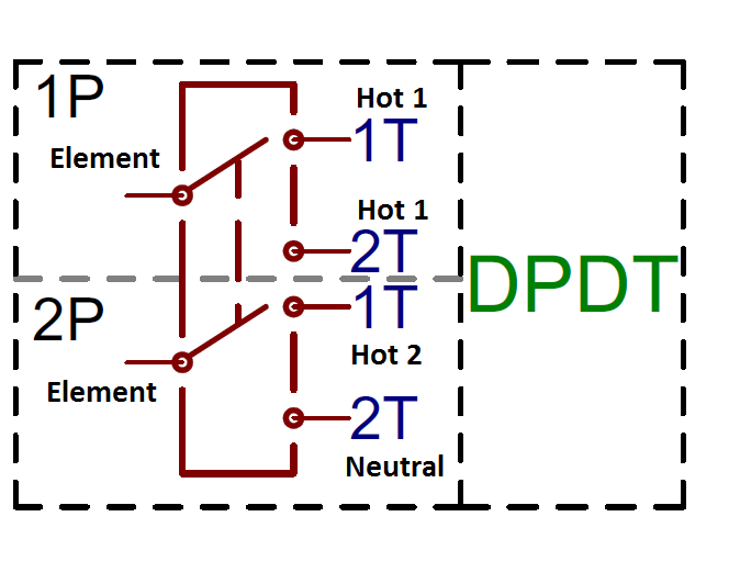
Another approach to this design is to use a DPDT relay to alternate a single 5500W element between full power (240v) and 25% power (120v)

Your low power side is a bit lower, but you don't have to buy and install a second element.

517edbabce395fd51d000000.png
 
Another approach to this design is to use a DPDT relay to alternate a single 5500W element between full power (240v) and 25% power (120v)

Your low power side is a bit lower, but you don't have to buy and install a second element.

Yeah, I've done designs for that as well, and that's how I plan to build my system.

Brew on :mug:
 
Hello doug293cz,

I've been pouring through the eBrew threads and This is exactly what I've been looking to put together, with the possibility of a Variable SSR for boil tuning.

Do you have the drawing of the dual voltage/single 5500W element design?

I'm also toying with Raspberry PI/StrangeBrew Elsinore as the controller, but I can figure out how to sub that in.

Any help/thoughts would be greatly appreciated..

Dave

That drawing is in the queue ('cause that's how my system will be built.) I would recommend the DSPR110, as it provides the same functionality as a PID plus an SSVR, without requiring any extra switching between the two. Adding the option for computer automation adds a bunch more switching if you want to be able to switch between manual and auto.

Edit: I do have an older dual voltage design, but it's not where I am heading now. But, here it is for what it's worth.

Edit2: Posted the wrong design. See below for correct design.

Brew on :mug:
 
Thanks for the super fast response.

I'll check out this design and look forward to seeing what you ultimately end up with for yourself.

Cheers...
 
Posted incorrect design above. Correct version is shown below. Note that the + and - connections on the SSR are incorrect (reversed.)

PID DSPR1 Pump 120V or 240V rev 2.PNG

Brew on :mug:
 
Ok, take a look at this design. I think it covers all of your requirements. My drawing program doesn't have a large enough selection of line widths, so I used the same width line to represent 12 AWG and 16 AWG wiring. Everything downstream of the 10A fuse can use 16 AWG, and the 120V element wiring requires 12 AVG. Of course, you can always use heavier wire than required for the amperage, but finer wire is easier to work with. Let me know if you have any questions.

View attachment 351723

Brew on :mug:

Hi Doug, Just starting to put together my parts list and have a couple of questions:
I don't see any kind of emergency stop. Is the GFCI tripping or turning off the main power switch-SW 8 act as an emergency off?
For the LED indicator lamps IND-1, the one for the 240v receptacle should be 240v, and the one for the 120v receptacle should be 120v, right? What about the "Element Power On" one illustrated between the 2 contactors? 120v?
For the SW16 pump switch-This should be wired to the NO block, correct? Then turning on the switch completes the circuit and powers the pump, if I am thinking correctly.

Thanks again for your help!
 
Thanks again......I had started looking at the original late last night and had a few questions...but the diagram change alleviated that.

This new diagram will help me out a bunch

I looked at the SSRs I have and saw where the +/- flip-flop is.

I plan on using a heavy-duty plastic toolbox to house the controller components. Do you see/have any concerns/issues with that as long as everything that needs a ground gets a ground?

Any static electricity issues?

Again, thanks...your efforts for the brewing community are awesome....:D
 
Is the GFCI tripping or turning off the main power switch-SW 8 act as an emergency off?
For the LED indicator lamps IND-1

That switch would cut all the power on the outside, but it will still have power inside. I prefer an approach like this to the "trip the GFCI" E-Stop, but others disagree. Personally, I use a switch after the SSR / Contactors and before the element. That means if something is going wrong in the kettle I can hit that switch to kill the element without losing the ability to pump/monitor temp/restart everything.

Both of those lights would need to be 240v the way I'm reading that wiring diagram.

Do you see/have any concerns/issues with that as long as everything that needs a ground gets a ground?

I use a plastic tool box for my controller, no issues as long as everything is well grounded. I like to double check my grounds from the wall plug through to the kettle every time I take anything apart.
 
I've been running a 120/240 EBIAB system for about a year now, although in a slightly different design.

My RIMS is the actual dual voltage part. The boil Kettle is 240 only. Part of my original thought was that I could run my RIMS on 120 (I have 2 supply cords, 1 for each voltage), and the kettle on propane when I want to take things on the road, but still use my RIMS & pump.
The other benefit to the 120/240 RIMS is that when I'm using 240 supply I can switch between 120 for RIMS use, and 240 for hitting strike temp quickly. My RIMS element is a 4500/240, so at 120 it's only 1125 watts. Mash ramps are possible with the 120 rating, but a little slow. I don't use it on 240 for RIMS to avoid any chance of scorching the wort.

If anyone is interested in the wiring give a shout and I'll post it later tonight.
Yes, I'd love to see your wiring diagram.

Brew on :mug:
 
Hi Doug, Just starting to put together my parts list and have a couple of questions:
I don't see any kind of emergency stop. Is the GFCI tripping or turning off the main power switch-SW 8 act as an emergency off?
For the LED indicator lamps IND-1, the one for the 240v receptacle should be 240v, and the one for the 120v receptacle should be 120v, right? What about the "Element Power On" one illustrated between the 2 contactors? 120v?
For the SW16 pump switch-This should be wired to the NO block, correct? Then turning on the switch completes the circuit and powers the pump, if I am thinking correctly.

Thanks again for your help!

The primary purpose of EPO switches on commercial equipment is to shut down any moving mechanisms, not electrical protection. So, the need for an EPO is debatable for an electric only panel. The key switch will kill all power coming out of the panel, and shut down any pumps, heaters, etc. powered by the panel. Any electrical fault to ground inside or downstream of the panel will trip the GFCI, so you don't need a special circuit to protect from those. Electrical faults from hot to hot, or hot to neutral will trip the main breaker or blow an internal fuse, and the wiring is sized to not burn up before the breaker trips.

The "Element Power On" and the "120V Element Firing" LED's are 120V, and the "240V Element Firing" LED is 240V. I thought I read somewhere you could use 240V LED's for all, but they will be slightly dimmer when driven by 120V, but I would test to be sure.

For the Pump Switch, you wire to an NO block. SW16's can be ordered with 2-NO or 1-NO, 1-NC configurations. SW1's have 2-NO blocks and no NC block.

Brew on :mug:
 
The indicator lights for the element on and element firing from the diagram need to 240V indicators correct?


Will the indicators be dimmer when the 120V is being used?
 

Latest posts

Back
Top