Butchhe
Well-Known Member
this. I need to live through other peoples build threads till i have the funds and time to work on my own.
+1

this. I need to live through other peoples build threads till i have the funds and time to work on my own.
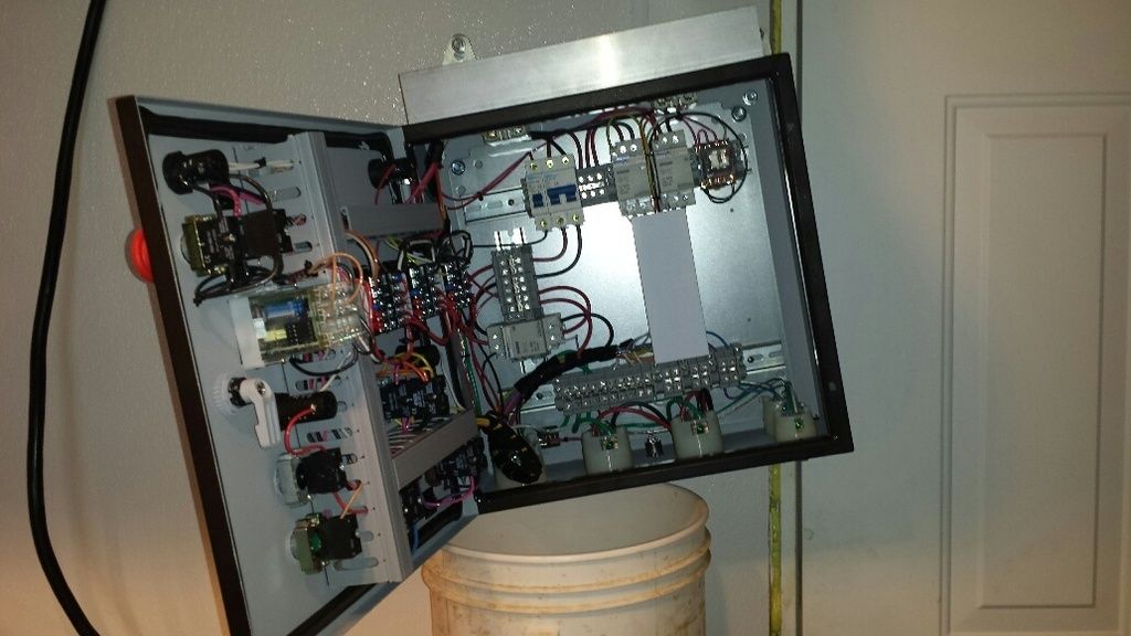
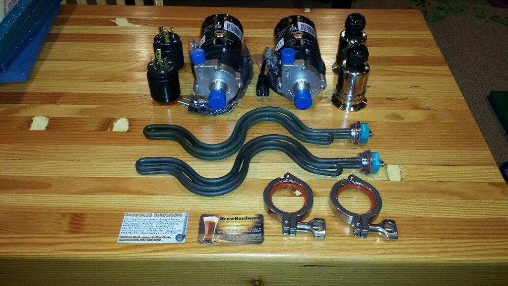
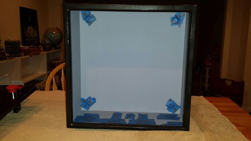
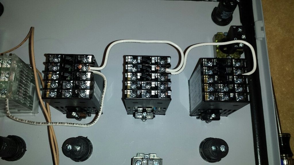
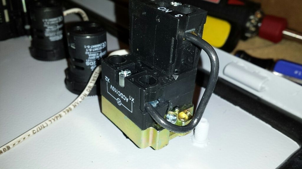
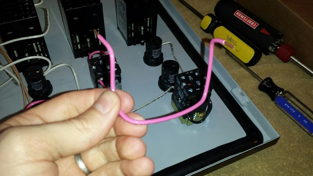
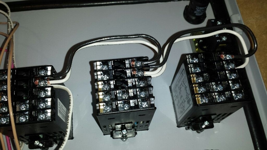
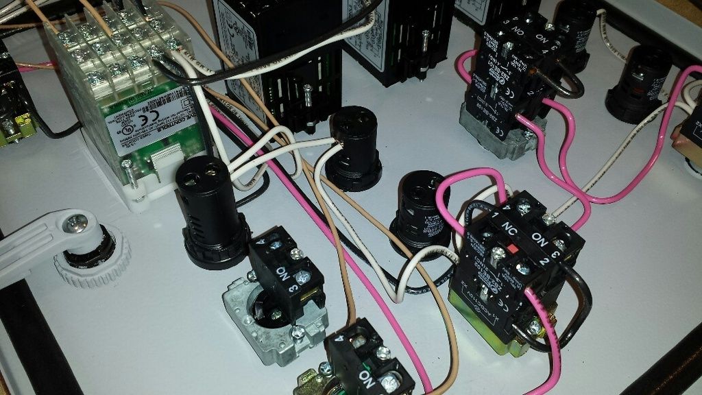
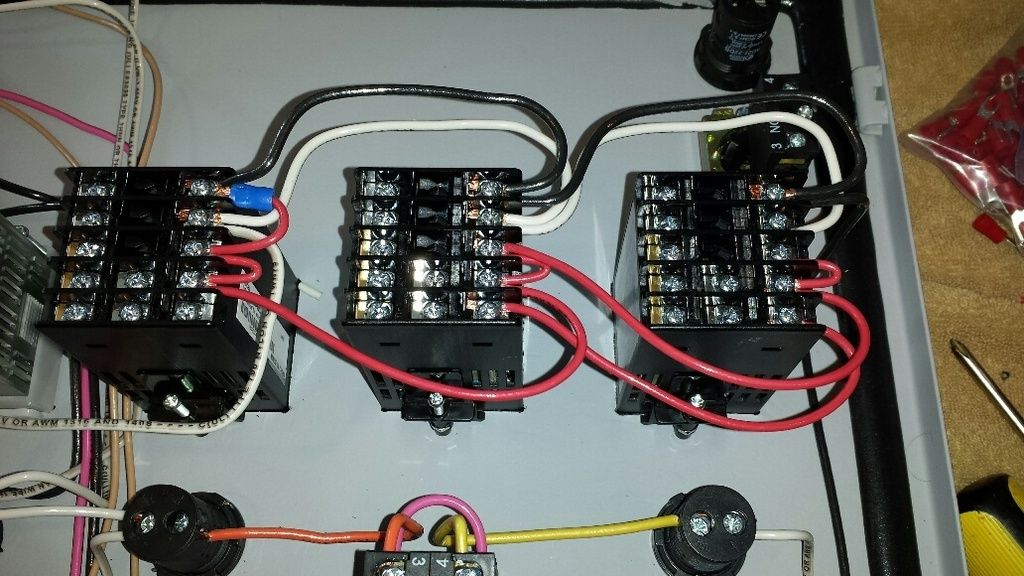
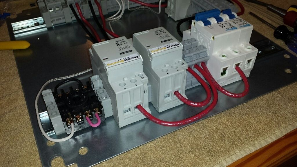
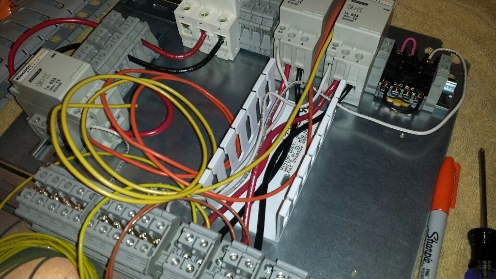
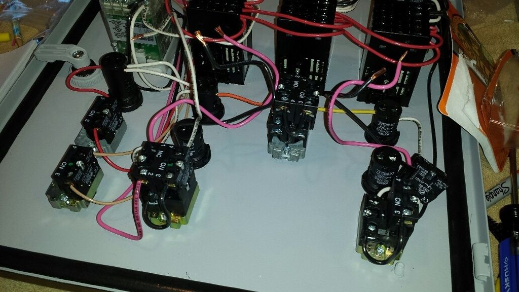
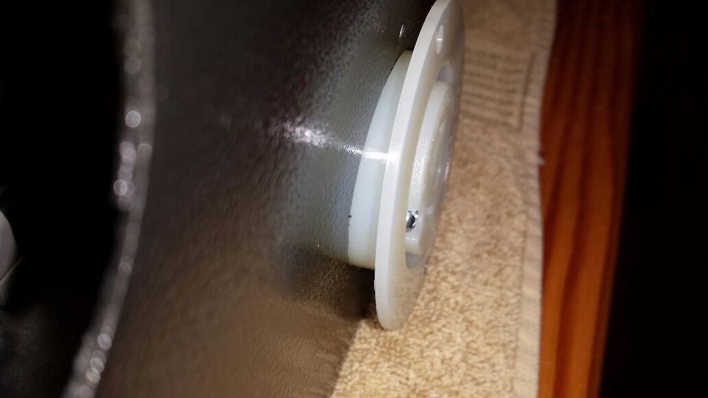
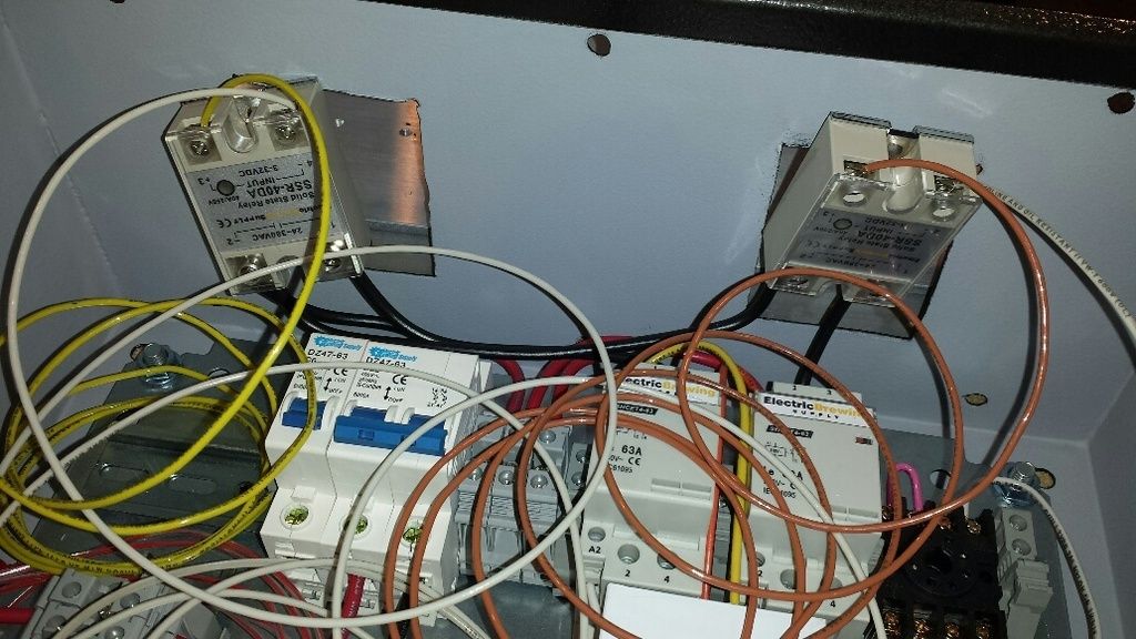
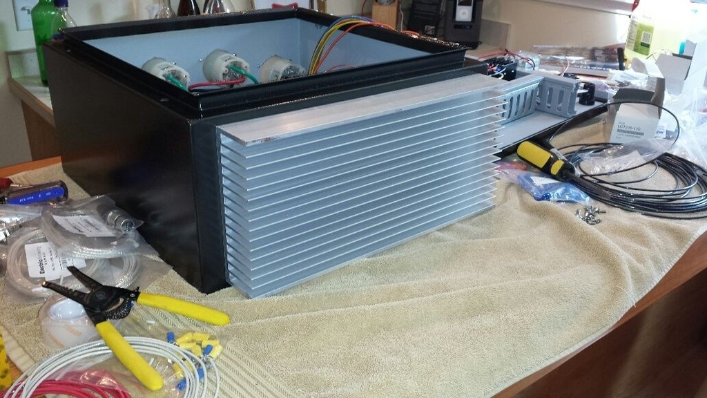
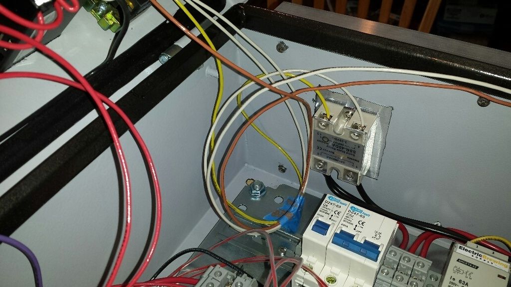
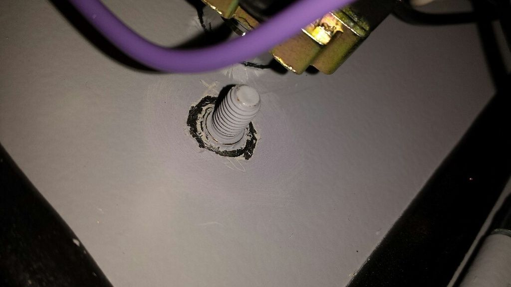
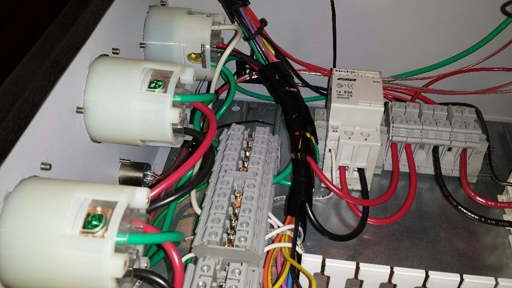
well, i can't promise a post every 15 minutes but i can certainly take frequent photos and summarize progress. a bit of a chore to document all this but i like to progress photos of my various projects anyway. i've learned so much from the photo-heavy threads and would like to return the favor.
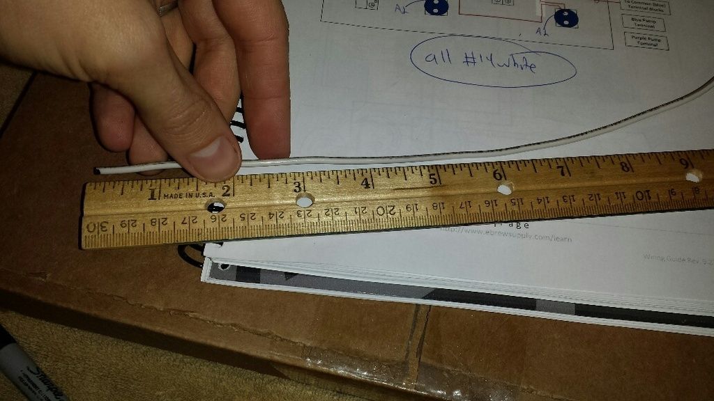
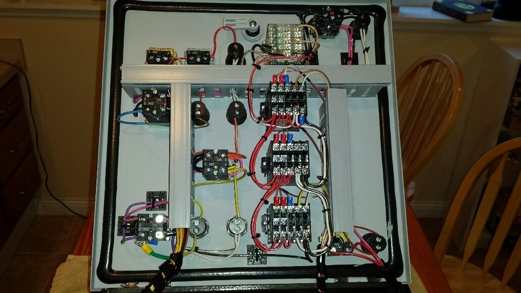
Your doing great on the photos. I would start working and not stop until I was done for the evening. Wouldn't even think about taking pictures of every step.
")


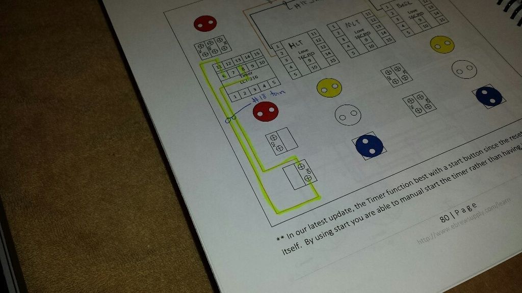
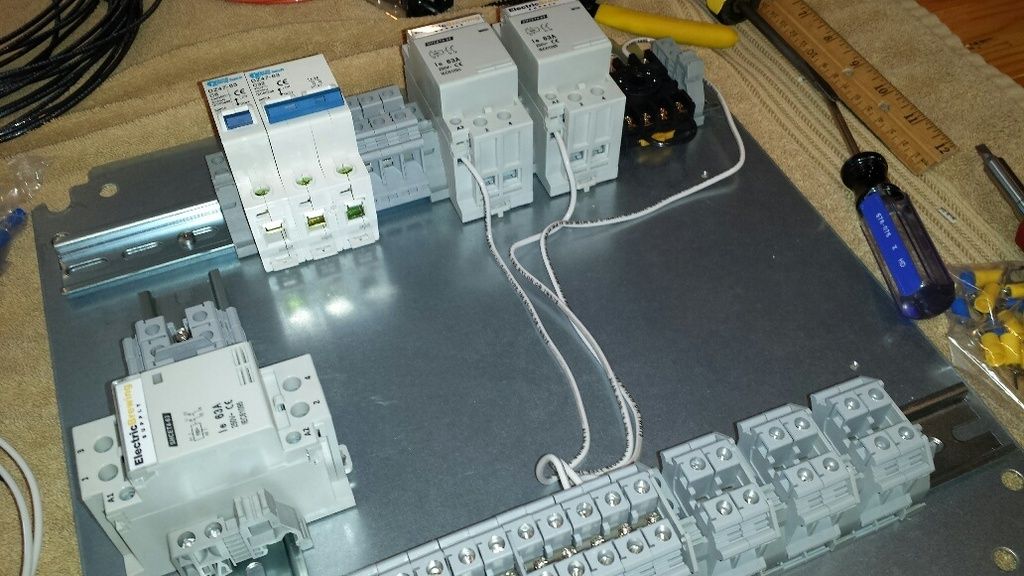
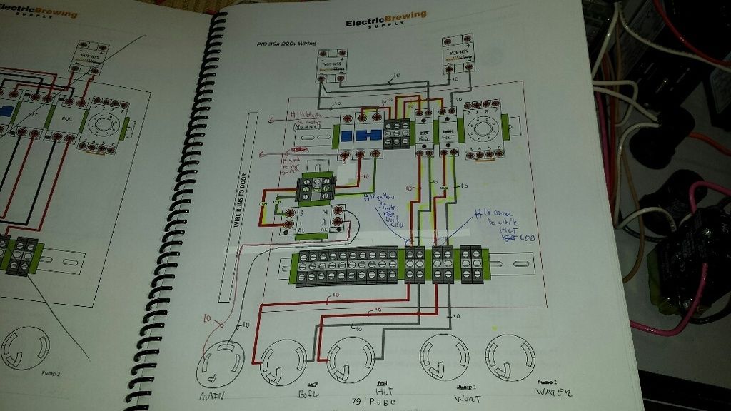
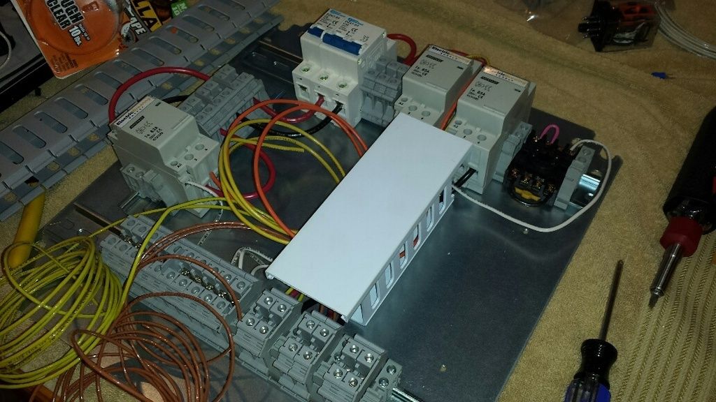
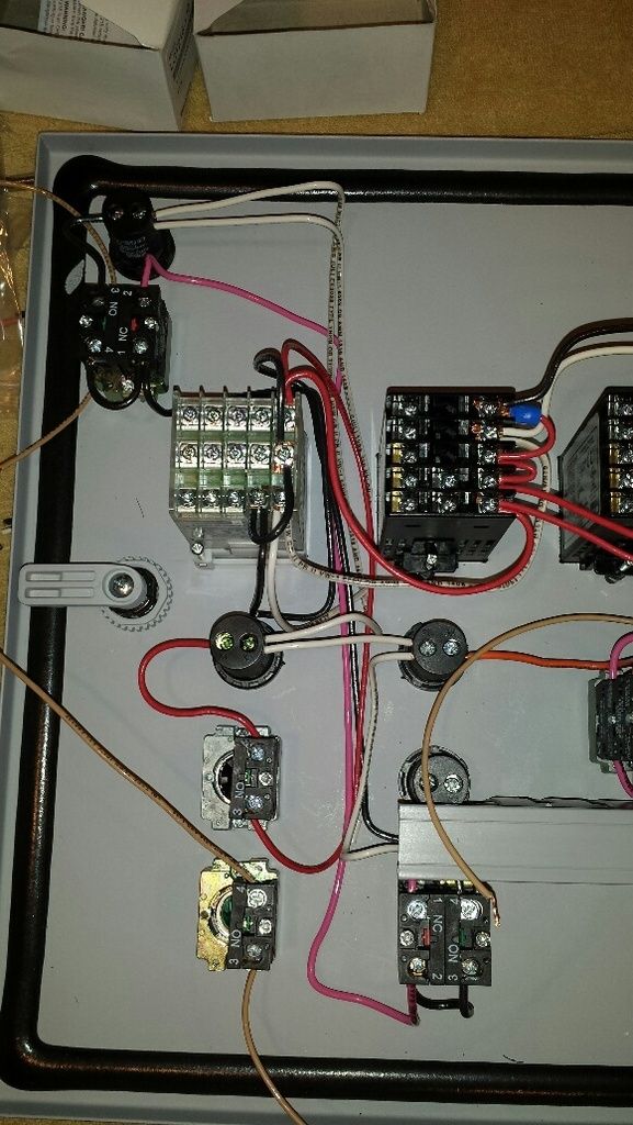
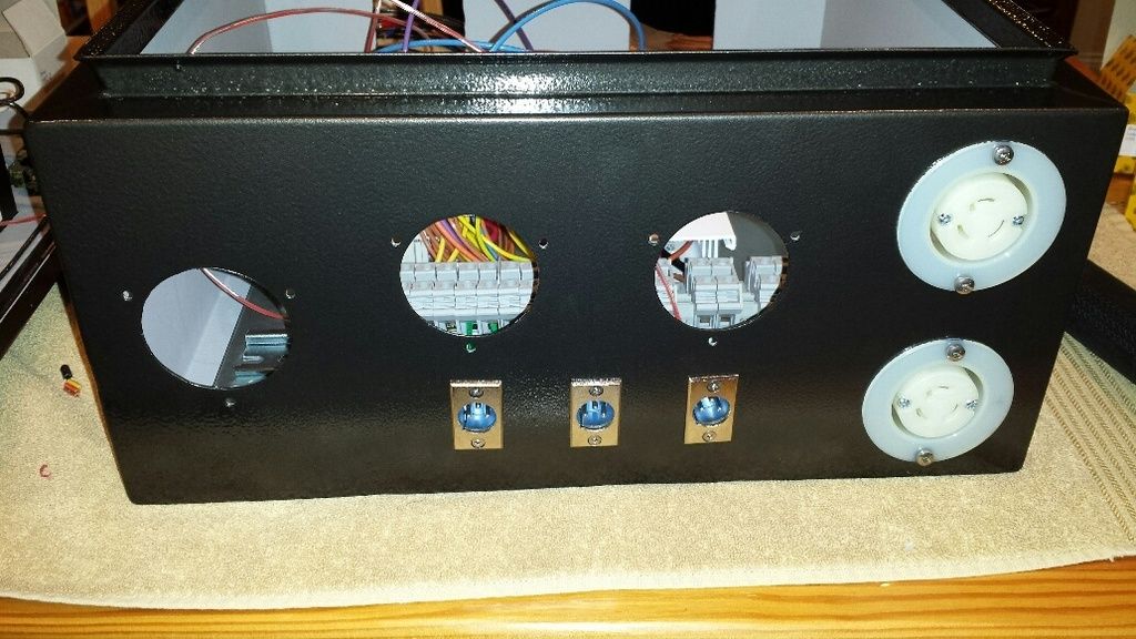
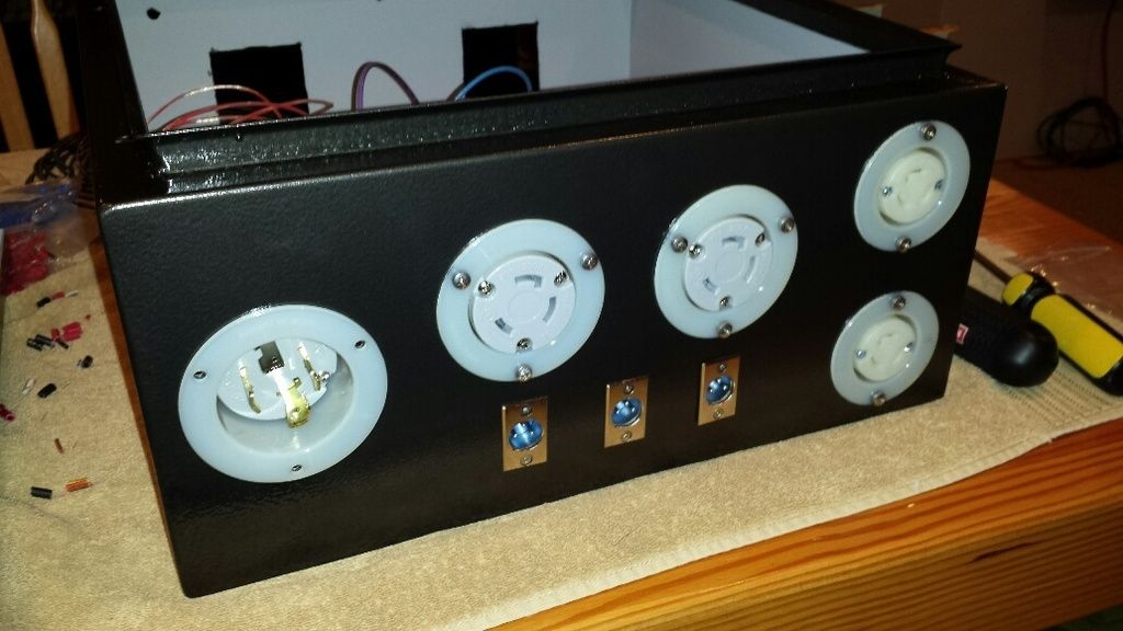

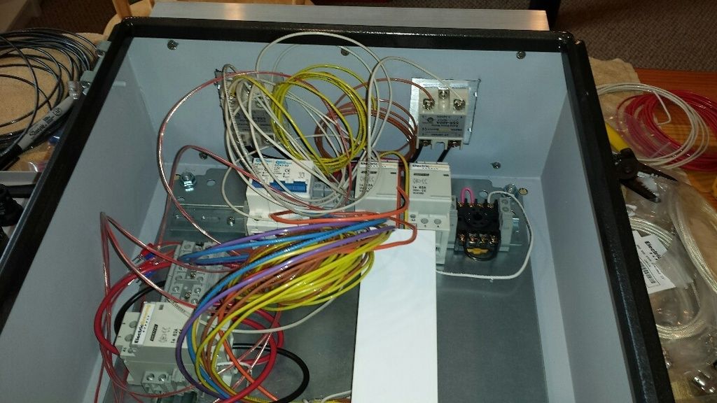
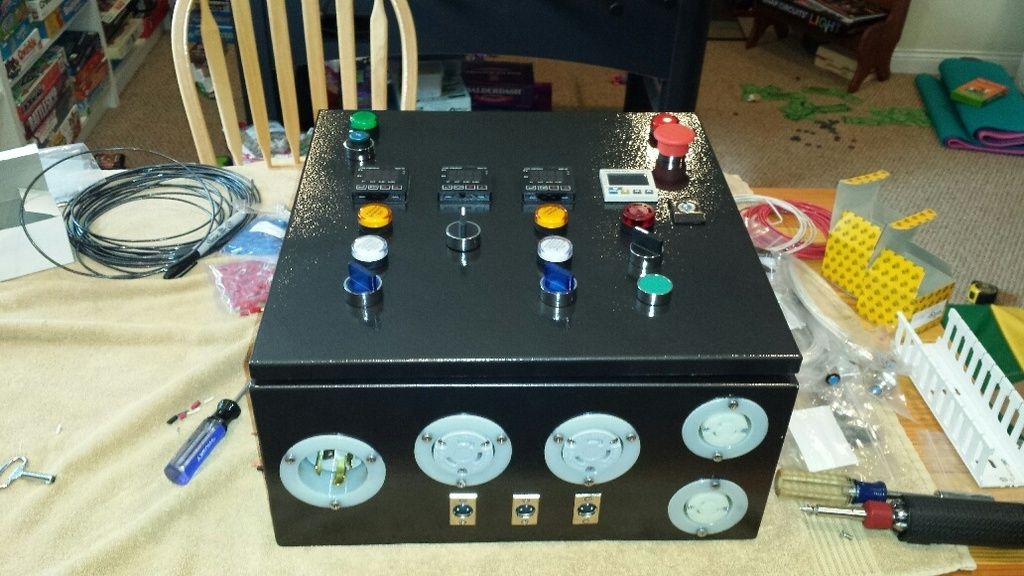
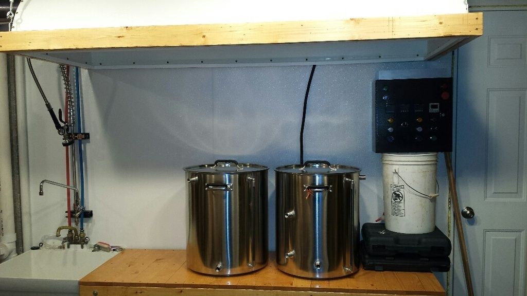
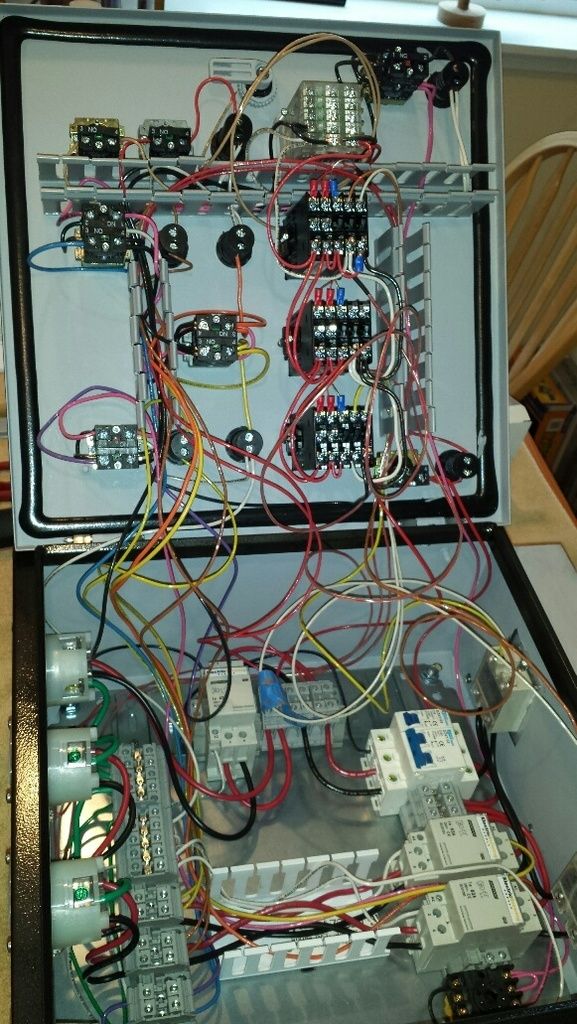
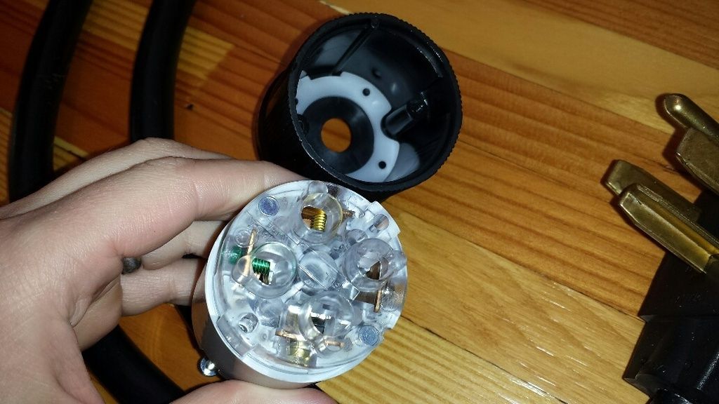
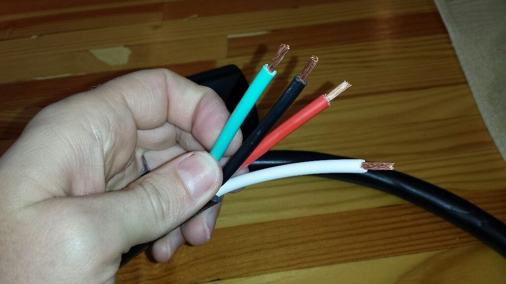
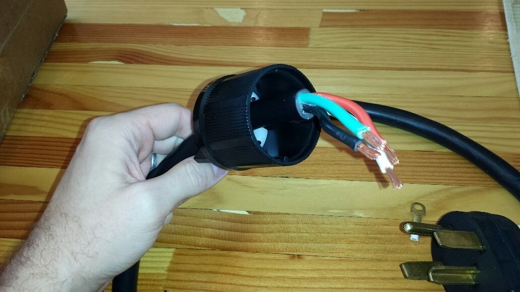
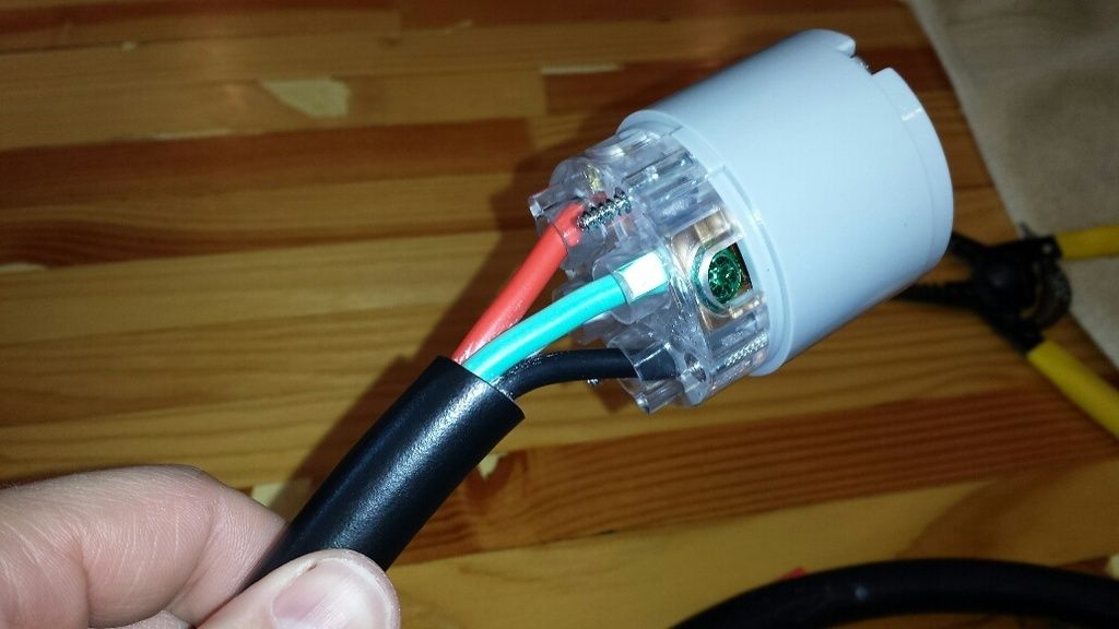
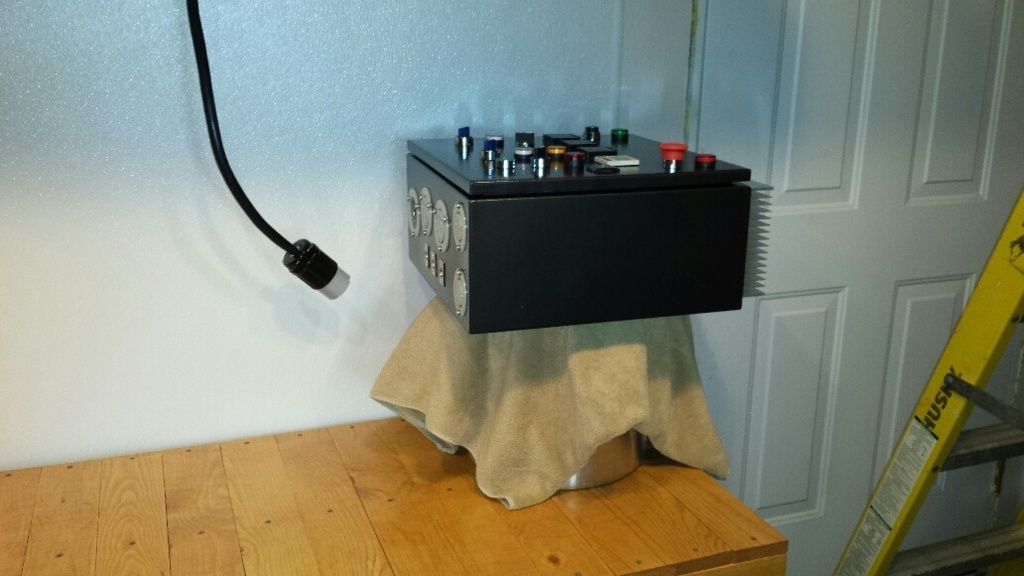
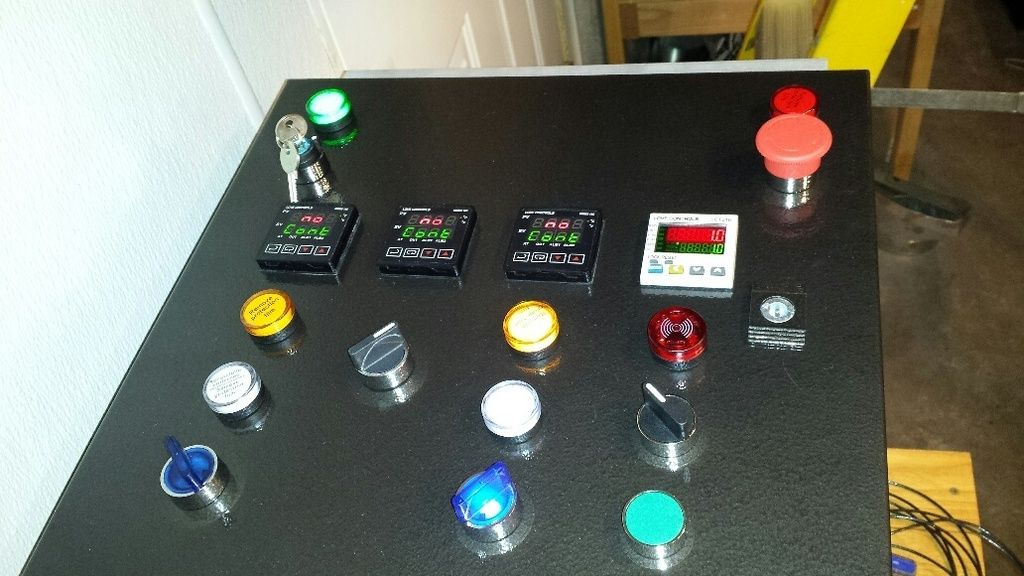
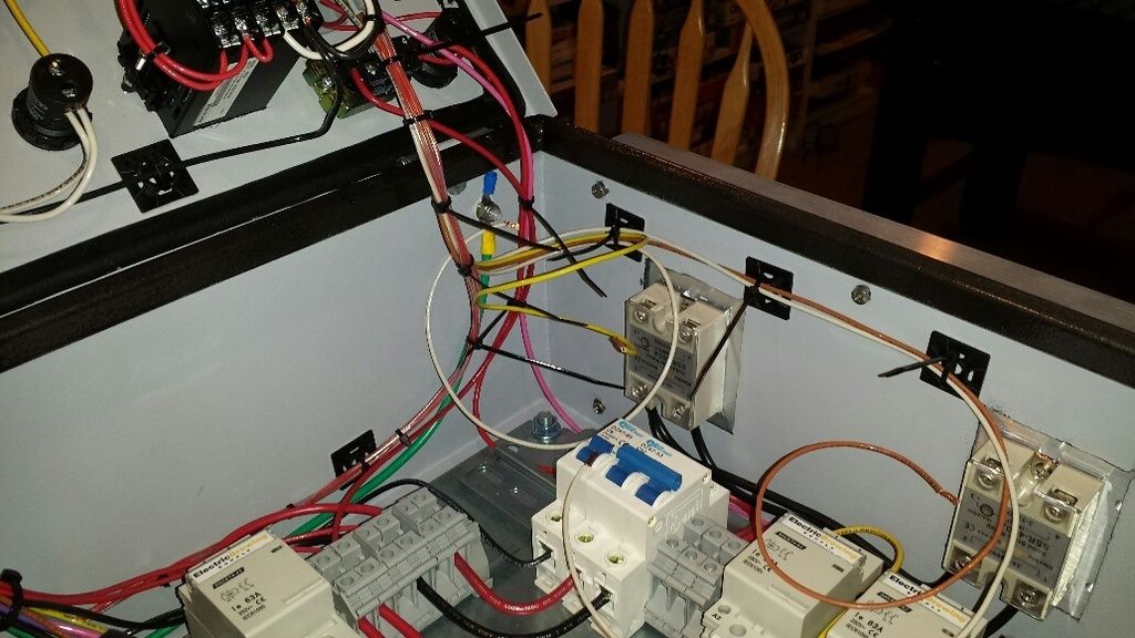
So happy you have the same control panel as I do. I'm stuck in Afghanistan for another 3 months so I'm unable to work on mine. Your step by step pictures are greatly appreciated! Don't be surprised if you get a PM from me in May when I start wiring again...in case I run into a snag. Great job! Keep the pictures coming!
Scott
This is impressive on so many fronts.
.
I am glad you are doing this yourself. This is real home brewing. All those people who buy their controllers and stuff already built, and brew in an already built kitchen are just posers and not really home brewing.
.
All fun aside. This is a wonderful thread to follow. That or talking the time to update us.
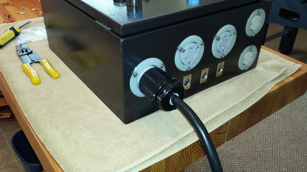
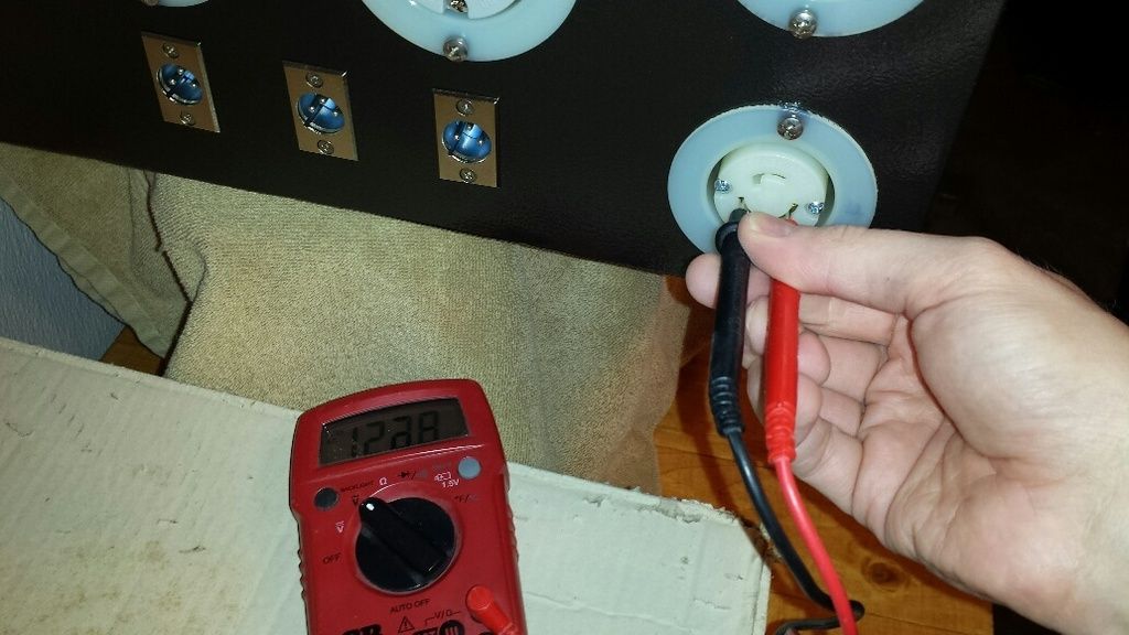
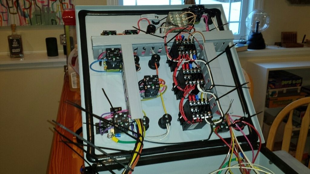
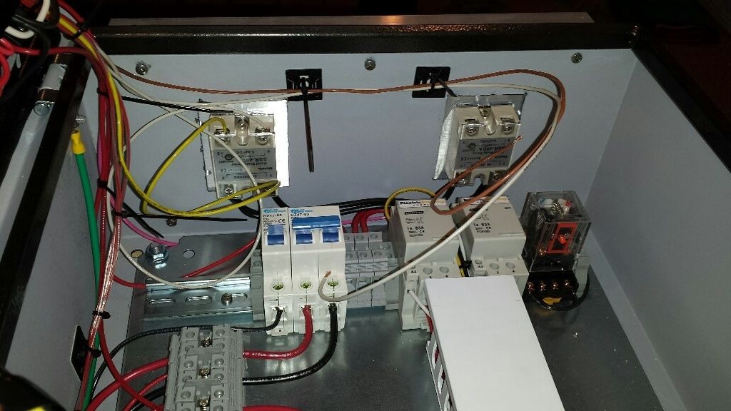
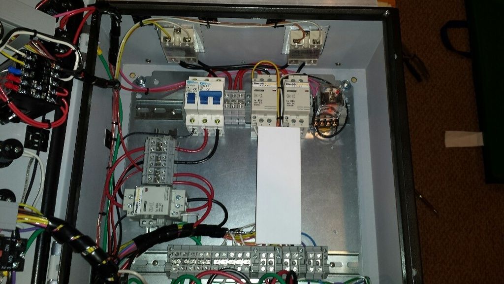
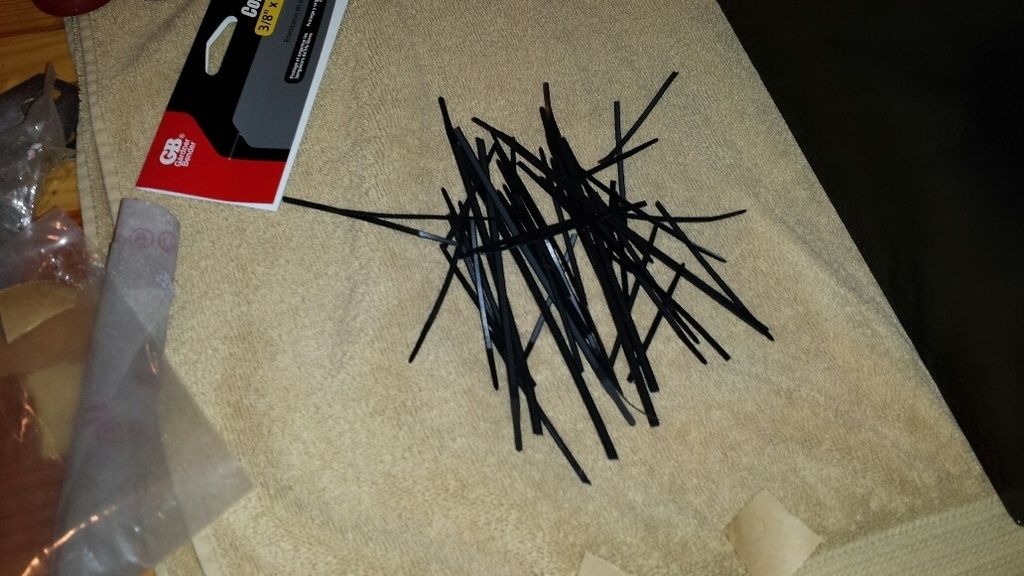
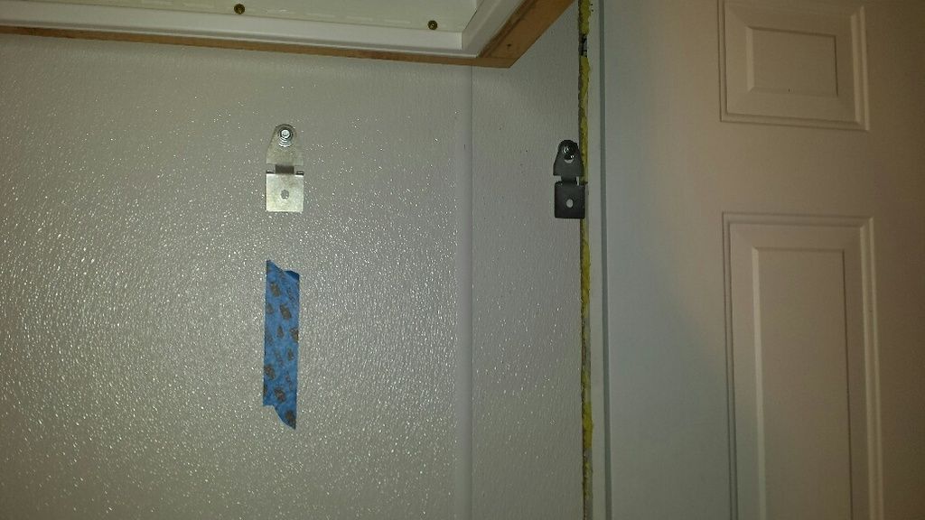
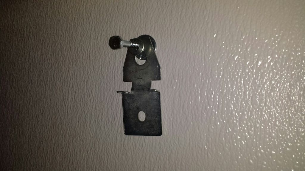
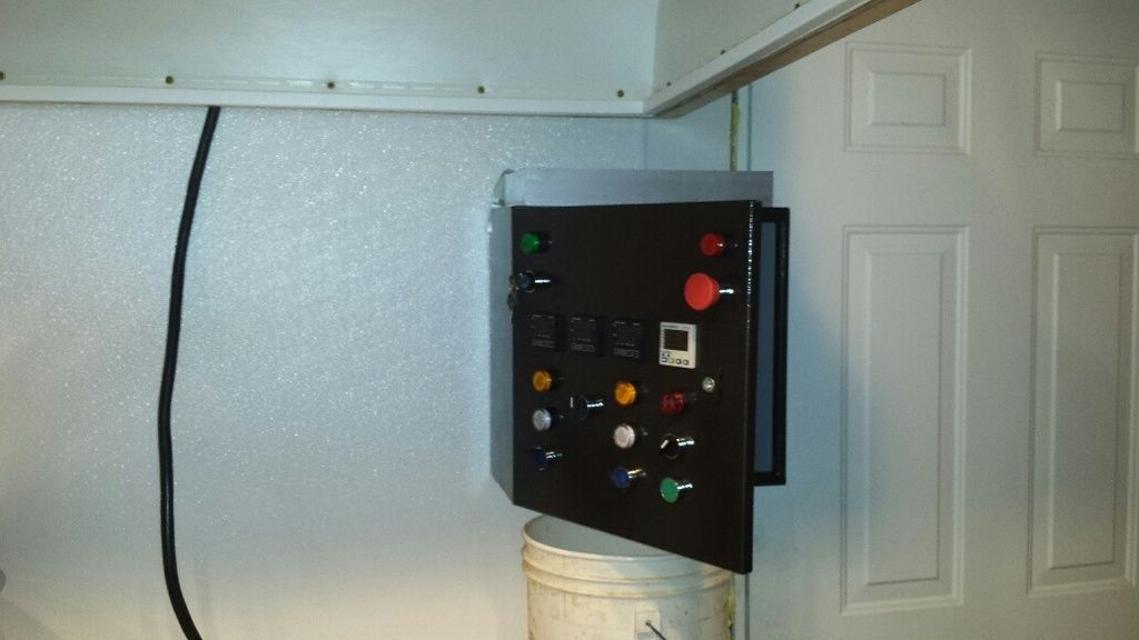
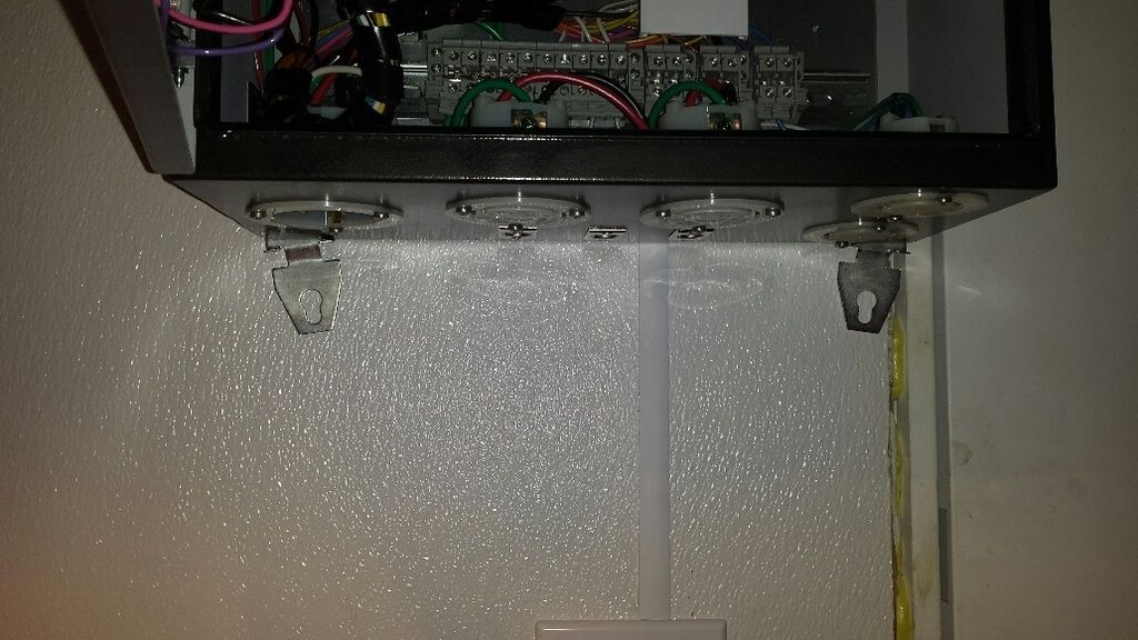
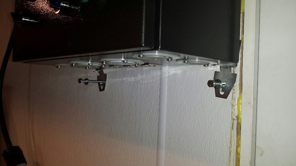
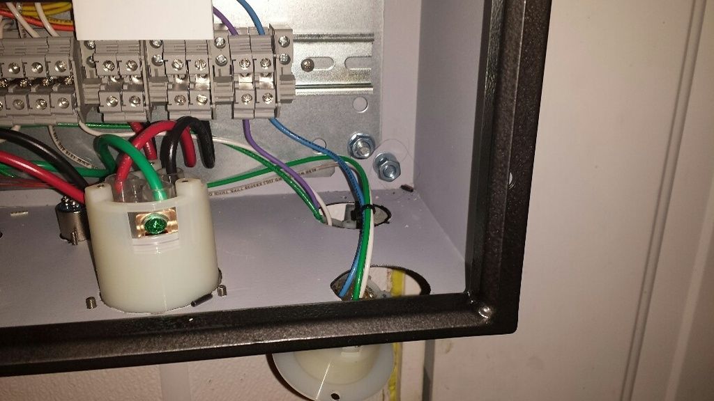
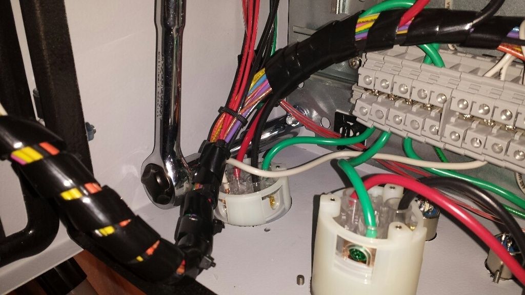
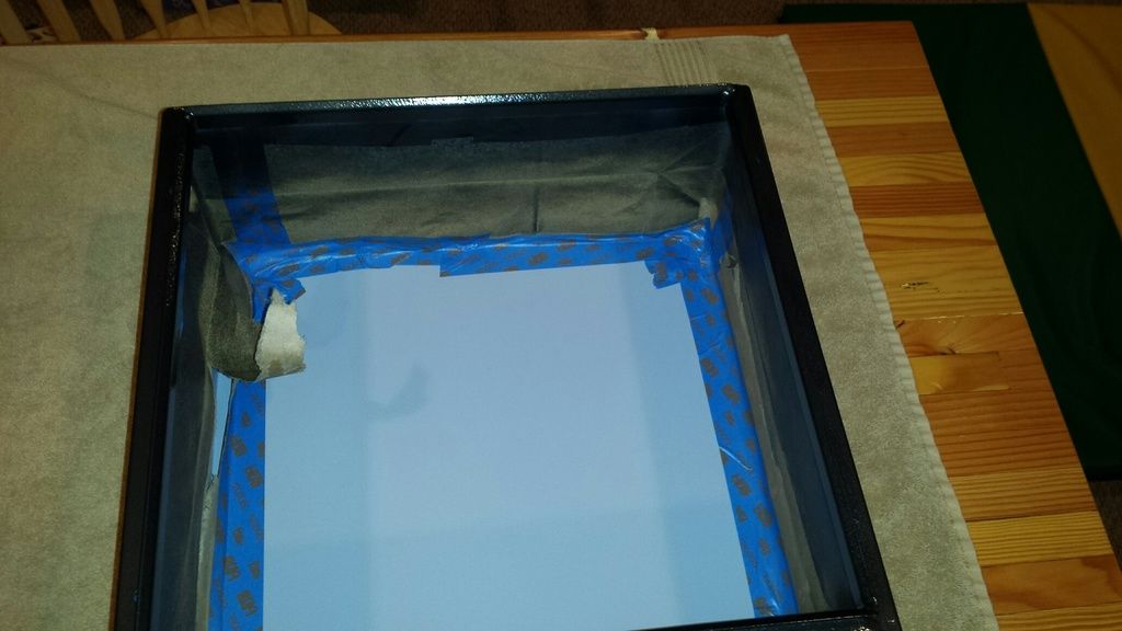
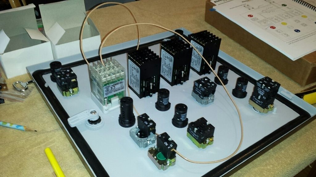
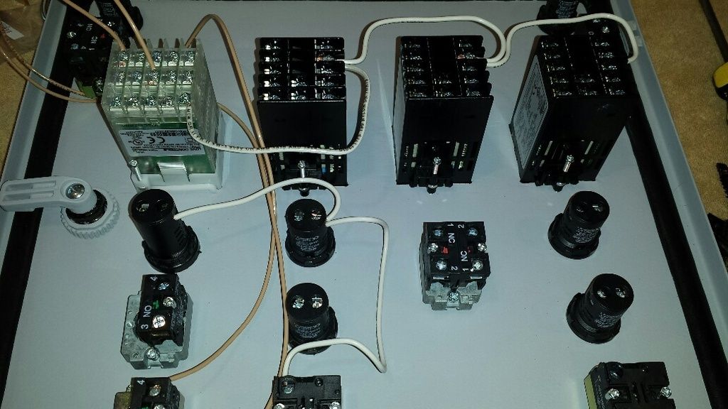
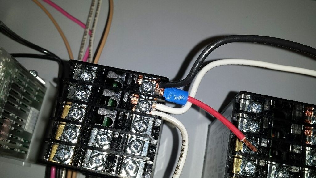
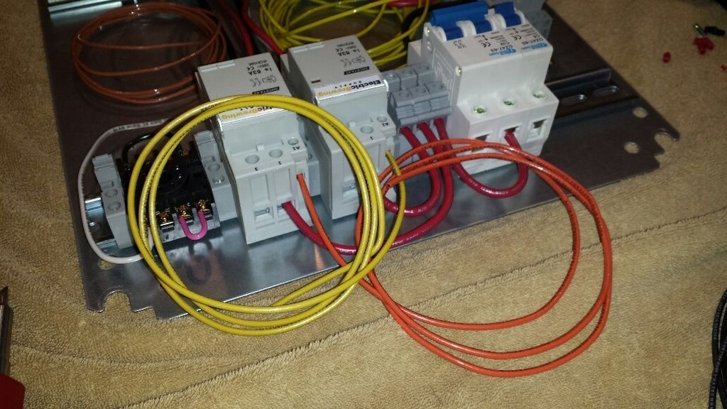
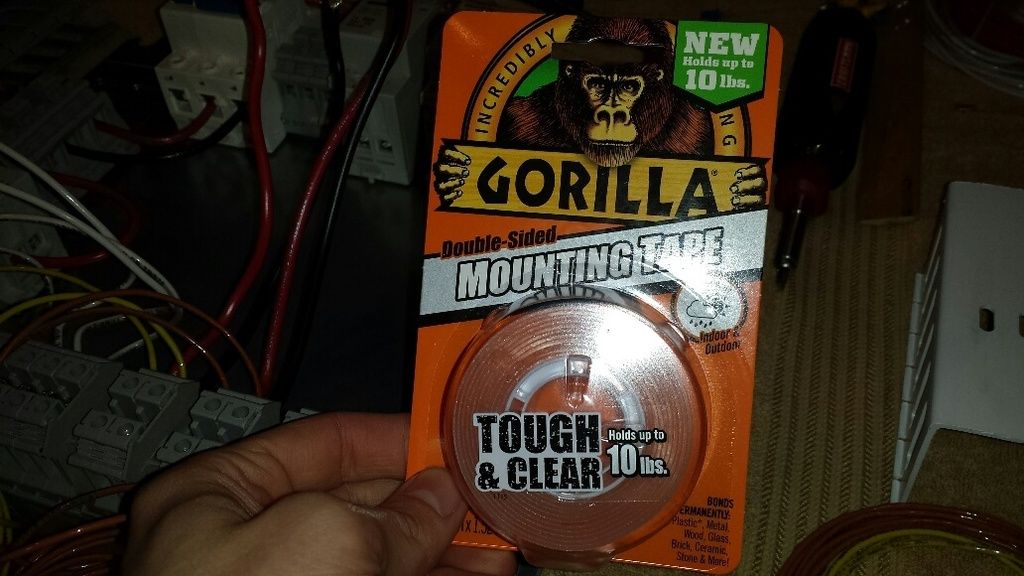
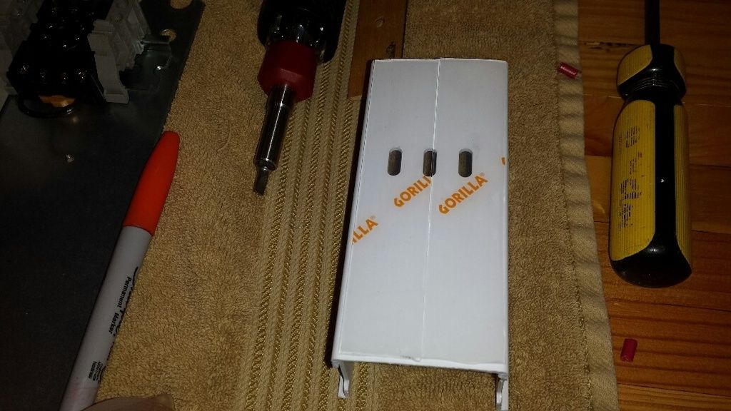
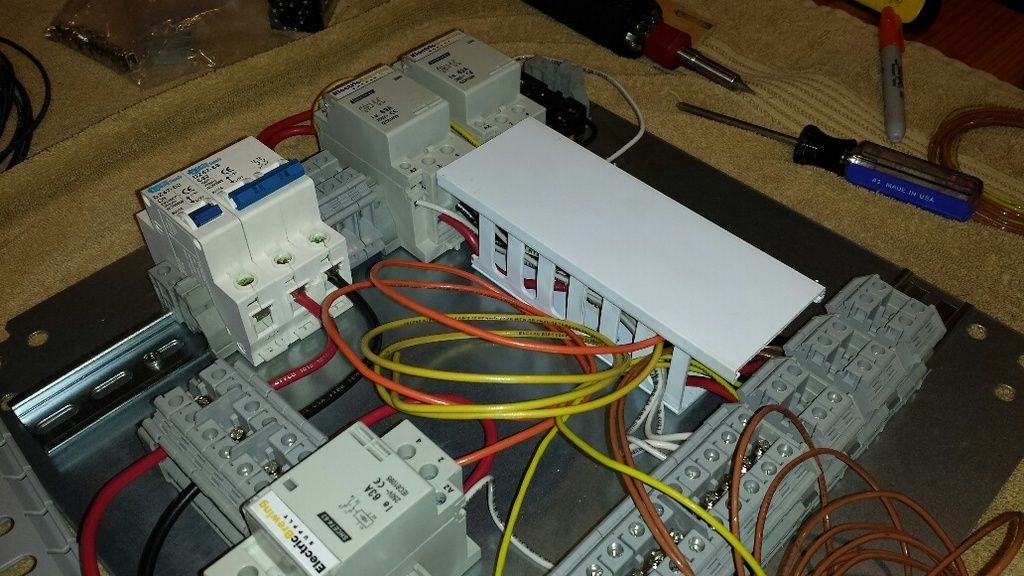
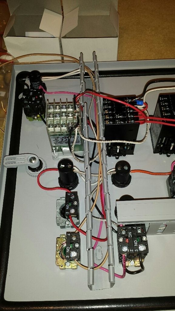
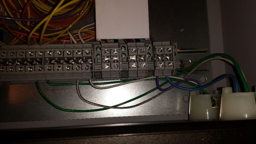
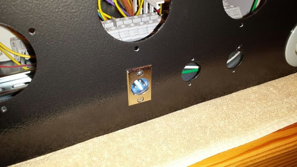
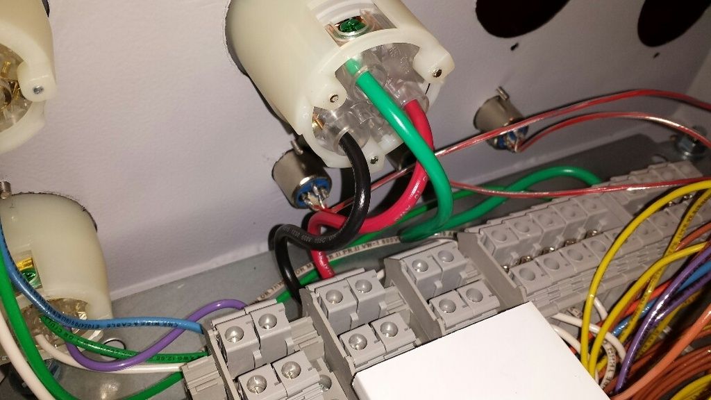
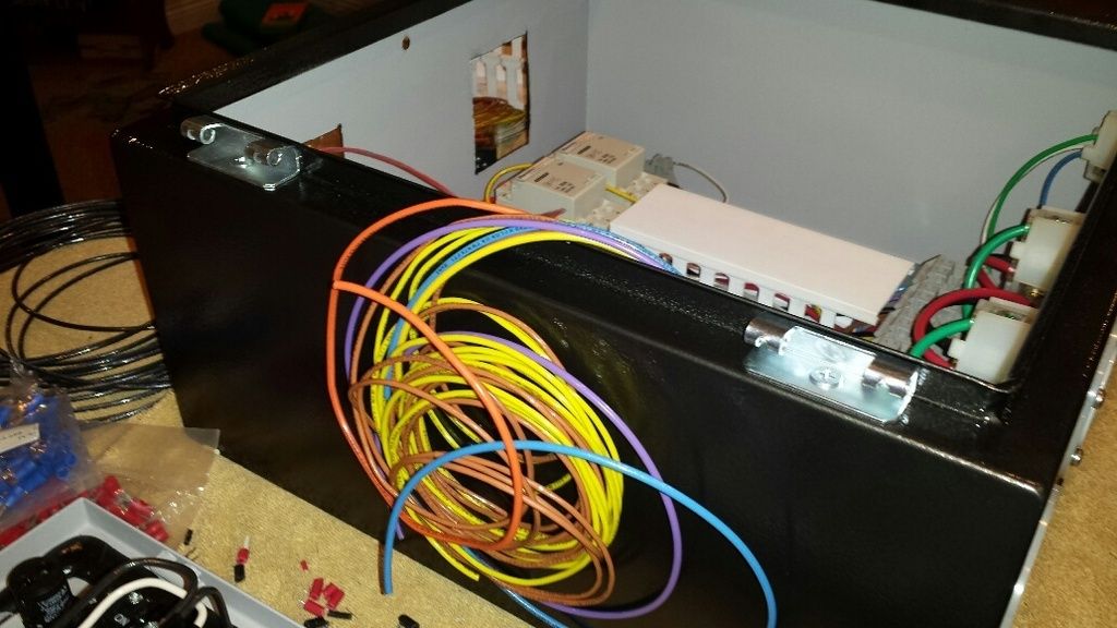
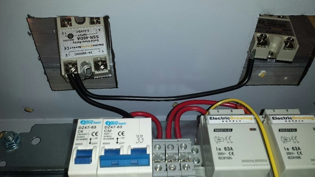
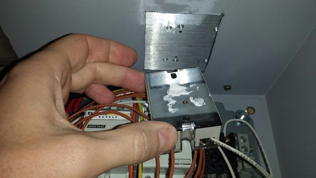
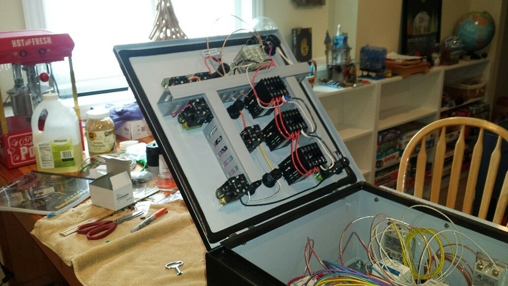
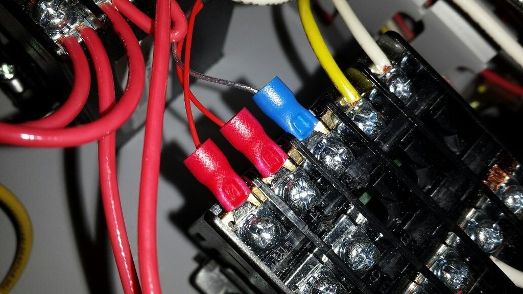
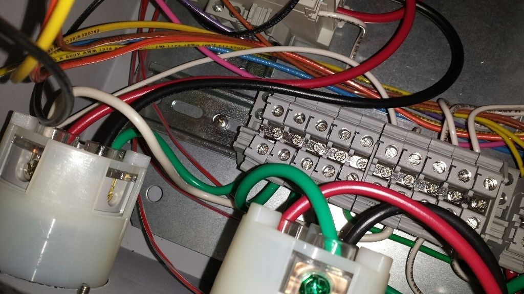
Awesome. Great job on the documentation. Minor FYI: adhesive tie downs are sometimes refrained from use in industrial applications because they do not hold well. Just make sure they don't have a lot of shear stress on them and you will be good.
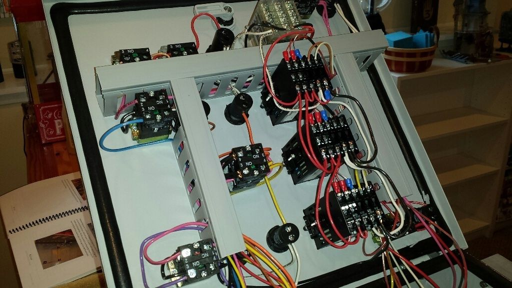
thanks for the support but i could not disagree with you more about people buying their control panel pre-built or brewing in a kitchen not being 'real' homebrewers. we all have different sets of skills, amounts of free time, etc. how do you know the guy buying an assembled panel didn't weld all his own fittings on his kettle? how do you know the guy/gal brewing with a picobrew isn't a single father/mother with essentially no free time?
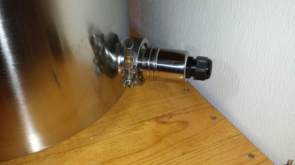
for me, i have the skill set to work with wiring and understand control systems. it wasn't worth the extra $550 to get my panel pre-built. but my kettles are a hole other story, i had no intentions of even trying to weld/cut a $300 stainless kettle. does that make me a 'poser'?