You are using an out of date browser. It may not display this or other websites correctly.
You should upgrade or use an alternative browser.
You should upgrade or use an alternative browser.
Hosehead/Brewtronix users
- Thread starter kcinpdx
- Start date

Help Support Homebrew Talk:
This site may earn a commission from merchant affiliate
links, including eBay, Amazon, and others.
jdr01
Well-Known Member
Thanks. Suppose I could leave a controller at both locations for now.
jdr01
Well-Known Member
Mine Hosehead died today. I hit the power switch and a electrical burning smell was apparent. The monitor went on then went black. Resetting a couple times did not help.
Out of commission for now.
My local HBS tried ordering some Blickman controllers but he says he can not get ahold of them.
Out of commission for now.
My local HBS tried ordering some Blickman controllers but he says he can not get ahold of them.
Mine Hosehead died today. I hit the power switch and a electrical burning smell was apparent. The monitor went on then went black. Resetting a couple times did not help.
Out of commission for now.
My local HBS tried ordering some Blickman controllers but he says he can not get ahold of them.
I still have a couple brewcommanders in stock.
jdr01
Well-Known Member
Thanks. Already picked them up from local store.

$53.24
1pc Hose Barb/MFL 1.5" Tri Clamp to Ball Lock Post Liquid Gas Homebrew Kegging Fermentation Parts Brewer Hardware SUS304(Liquid Hose Barb)
Guangshui Weilu You Trading Co., Ltd

$719.00
$799.00
EdgeStar KC2000TWIN Full Size Dual Tap Kegerator & Draft Beer Dispenser - Black
Amazon.com

$53.24
1pc Hose Barb/MFL 1.5" Tri Clamp to Ball Lock Post Liquid Gas Homebrew Kegging Fermentation Parts Brewer Hardware SUS304(Liquid Hose Barb)
yunchengshiyanhuqucuichendianzishangwuyouxiangongsi

$159.50 ($26.58 / Count)
3M High Flow Series System BREW120-MS, 5616001, For Brewed Coffee and Hot Tea, Valve-in-Head Design
Amazon.com

$58.16
HUIZHUGS Brewing Equipment Keg Ball Lock Faucet 30cm Reinforced Silicone Hose Secondary Fermentation Homebrew Kegging Brewing Equipment
xiangshuizhenzhanglingfengshop

$33.99 ($17.00 / Count)
$41.99 ($21.00 / Count)
2 Pack 1 Gallon Large Fermentation Jars with 3 Airlocks and 2 SCREW Lids(100% Airtight Heavy Duty Lid w Silicone) - Wide Mouth Glass Jars w Scale Mark - Pickle Jars for Sauerkraut, Sourdough Starter
Qianfenie Direct

$176.97
1pc Commercial Keg Manifold 2" Tri Clamp,Ball Lock Tapping Head,Pressure Gauge/Adjustable PRV for Kegging,Fermentation Control
hanhanbaihuoxiaoshoudian

$7.79 ($7.79 / Count)
Craft A Brew - LalBrew Voss™ - Kveik Ale Yeast - For Craft Lagers - Ingredients for Home Brewing - Beer Making Supplies - (1 Pack)
Craft a Brew

$44.99
$49.95
Craft A Brew - Mead Making Kit – Reusable Make Your Own Mead Kit – Yields 1 Gallon of Mead
Craft a Brew

$22.00 ($623.23 / Ounce)
AMZLMPKNTW Ball Lock Sample Faucet 30cm Reinforced Silicone Hose Secondary Fermentation Homebrew Kegging joyful
无为中南商贸有限公司

$10.99 ($31.16 / Ounce)
Hornindal Kveik Yeast for Homebrewing - Mead, Cider, Wine, Beer - 10g Packet - Saccharomyces Cerevisiae - Sold by Shadowhive.com
Shadowhive
jdr01
Well-Known Member
Sent PM
jdr01
Well-Known Member
Does anyone know if the temperature probes from the hosehead are compatible with any thermometers. I tried with two thermometers I have and they did not work. I like where I have all the probes located now. The brew commander only comes with one probe.
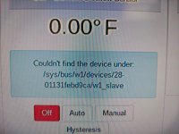
Hello everyone, I have been trying to get ahold of corey for a while from hosehead, and no response. Not sure what's going on, but i have a question, maybe someone can answer here. I have a hosehead controller 5BC i think, with the first raspberry pi that was wifi capable, i think the 3. I spent a day brewing, shut down, cleaned my equipment, and fired the system back up to roll boiling water through my lines, and the controller stopped working. It said it couldn't find the IP address for the raspberry pi. I've tried everything, including the instructions in the controller to completely re-install the software, no avail. Does anyone have any suggestions? I have to get 2 beers for our xmas party ready to rock, and i'm wondering, should i just go buy a new controller now and hope i get it asap? I can't find anything with 50 amp for 2 heater elements, so i'd have to completely redo my electrical box to support 2 30 amp plugs as well as add 2 new outlets and wire myself, for anything i'm finding on google. Any advice would be amazing!!
my email is [email protected] if anyone has any good advice to offer, thanks much, in a time pinch here, lol.
my email is [email protected] if anyone has any good advice to offer, thanks much, in a time pinch here, lol.
- Joined
- Nov 6, 2008
- Messages
- 26
- Reaction score
- 7
Hello everyone, I have been trying to get ahold of corey for a while from hosehead, and no response. Not sure what's going on, but i have a question, maybe someone can answer here. I have a hosehead controller 5BC i think, with the first raspberry pi that was wifi capable, i think the 3. I spent a day brewing, shut down, cleaned my equipment, and fired the system back up to roll boiling water through my lines, and the controller stopped working. It said it couldn't find the IP address for the raspberry pi. I've tried everything, including the instructions in the controller to completely re-install the software, no avail. Does anyone have any suggestions? I have to get 2 beers for our xmas party ready to rock, and i'm wondering, should i just go buy a new controller now and hope i get it asap? I can't find anything with 50 amp for 2 heater elements, so i'd have to completely redo my electrical box to support 2 30 amp plugs as well as add 2 new outlets and wire myself, for anything i'm finding on google. Any advice would be amazing!!
my email is [email protected] if anyone has any good advice to offer, thanks much, in a time pinch here, lol.
Could be that the sd card got corrupted. I had my controller die after a power surge along with my temperature sensors. Got a new card, reloaded, replaced the sensors. One way to check is to open it up and connect the HDMI port to a tv or monitor, turn it on and see if it boots.
Hello everyone, I have been trying to get ahold of corey for a while from hosehead, and no response. Not sure what's going on, but i have a question, maybe someone can answer here. I have a hosehead controller 5BC i think, with the first raspberry pi that was wifi capable, i think the 3. I spent a day brewing, shut down, cleaned my equipment, and fired the system back up to roll boiling water through my lines, and the controller stopped working. It said it couldn't find the IP address for the raspberry pi. I've tried everything, including the instructions in the controller to completely re-install the software, no avail. Does anyone have any suggestions? I have to get 2 beers for our xmas party ready to rock, and i'm wondering, should i just go buy a new controller now and hope i get it asap? I can't find anything with 50 amp for 2 heater elements, so i'd have to completely redo my electrical box to support 2 30 amp plugs as well as add 2 new outlets and wire myself, for anything i'm finding on google. Any advice would be amazing!!
my email is [email protected] if anyone has any good advice to offer, thanks much, in a time pinch here, lol.
If you would be interested in converting your controller to BruControl, you could swap the internal RPi for an ESP-32 microcontroller (about $15) and be up and running pretty quickly. I realize it’s a different system with some learning curve, but since you have the power hardware already, it’s a potential option.
carrsgarage
Well-Known Member
- Joined
- Apr 19, 2018
- Messages
- 98
- Reaction score
- 11
If you would be interested in converting your controller to BruControl, you could swap the internal RPi for an ESP-32 microcontroller (about $15) and be up and running pretty quickly. I realize it’s a different system with some learning curve, but since you have the power hardware already, it’s a potential option.
@BrunDog - I've got a Hosehead that has served me pretty well, but I REALLY like what you've done with BruControl and have been considering upgrading for a while. Is it really as simple as swapping the Pi for an ESP-32? The only thing that's been holding me back is the investment in more hardware and a computer to run the software on.
I haven't actually done it... and I can't find any pictures online of the insides, but in theory these are the considerations:
- The ESP32 needs 5V power... either through the pins or the USB connector. Assuming the RPi was powered the same way, you should be good to go.
- The ESP32 is a 3.3V device, as is the RPi. Just need to make sure the SSRs and/or relays inside don't over-current the ESP32. Assuming the RPi's I/O could power those devices, so should the ESP32.
- The 1-wire sensors should work OK... remember to include the pull-up resistor.
- IIRC, the hosehead was connecting via Ethernet? The RPi has WiFi too, just not sure if it was used. If it was inside a metal enclosure, then the signal will be crappy. I would suggest an ESP32U which has the external antenna port. That plus the external antenna and you can connect via WiFi really well.
carrsgarage
Well-Known Member
- Joined
- Apr 19, 2018
- Messages
- 98
- Reaction score
- 11
I'll try to get some pictures up later today. I've had mine open numerous times and I'm pretty sure it's still apart.
carrsgarage
Well-Known Member
- Joined
- Apr 19, 2018
- Messages
- 98
- Reaction score
- 11
@BrunDog
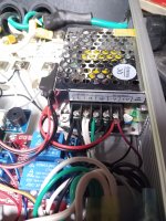
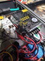
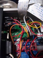
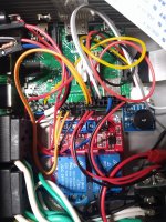
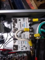
Here's what I see:
120 VAC (Pumps and Pi) Side:
120 VAC through an On/Off switch into a DC Power Supply.
The 120 VAC also runs from the On/Off switch into the Commons of a 2 Relay Module. The Normally Open contacts of the 2 Relay Module are connected to the 2 Pump outlets.
From the DC Power Supply, power runs through something small with a heat sink on it, then to the 2 Relay Module and the Raspberry Pi.
Power comes off the 2 Relay Module power pins and goes through a 100ma - 500ma 5x20mm fuse to the 1-wire jack. There is a resistor between the +DC terminal and the terminal that runs back to the Pi.
Inputs 1 & 2 on the 2 Relay Module run to GPIO pins on the Pi.
240 VAC (Heating Elements) Side:
Black wire - to the 2/T1 lugs of the SSRs.
Red wire - spliced to the white wire of each of the NEMA 6 outlets.
Green wire - spliced to the green wire of each of the NEMA 6 outlets.
The black wire of each NEMA 6 outlet is wired to 1/L1 on one of the SSRs.
4/A2- of the SSRs is wired to an On/Off switch, then to the DC Power Supply. Also wired to this switch is the top-mounted cooling fan.
+3/A1 of each SSR is wired to a GPIO pin on the Pi.
And there you have it.


This is a 50A unit?
carrsgarage
Well-Known Member
- Joined
- Apr 19, 2018
- Messages
- 98
- Reaction score
- 11
Yes, it is the 5BC 3 B+
Allow me a safety marshal minute… With all due respect to the developer, I feel the need to disclaim the relative danger inherent in the design (from what I can see). The 50A supply is shared without any current limitations down circuits which are meant for, and should be capped at, 30A. The full 50A can go through the SSRs and into to heater outputs. That means that much current *can* make its way to the elements.
Assuming the wires supporting those circuits are 10 AWG, they will be are overloaded. Maybe they just get hot, but the terminals and respective posts will probably overheat and fail rapidly, potentially damaging their connections and causing a fire. In combination with a lack of circuit interrupt, you have multiple potential risk points between always hot legs and current overload.
That said, if you are cool with this high voltage design, the low voltage part is relatively easy. Assuming that heat sink module outputs 5V or 3.3V, either can power the ESP32. The power to the 1-wire should be 3.3V - not 5V (the RPi GPIO pins are 3.3V - it’s possible ther are seeing 5V here.
Pardon me here: ironic that there is a fuse to the 1-wire sensors, but the 50A input is free to roam…
Last edited:
repetesbh
Member
- Joined
- Jan 8, 2022
- Messages
- 14
- Reaction score
- 8
My Hosehead just started reporting it could not find my sensor for my yellow/BK. It still recognized the HLT and MT sensors. I think I have either a corruption issue or a bad sensor. How difficult was it to replace the sensors? How much reprogramming did you need to do?Could be that the sd card got corrupted. I had my controller die after a power surge along with my temperature sensors. Got a new card, reloaded, replaced the sensors. One way to check is to open it up and connect the HDMI port to a tv or monitor, turn it on and see if it boots.
Any help/advise would be great.
Cheers!
Attachments
- Joined
- Nov 6, 2008
- Messages
- 26
- Reaction score
- 7
My Hosehead just started reporting it could not find my sensor for my yellow/BK. It still recognized the HLT and MT sensors. I think I have either a corruption issue or a bad sensor. How difficult was it to replace the sensors? How much reprogramming did you need to do?
Any help/advise would be great.
Cheers!
Probably a bad sensor since the rest of the system is working. I don't have a Hosehead, I built my own controller and used Strangebrew. The sensors are DS18B20 one wire sensors, you can find them on Amazon and various other places. Then you'd have to change the address associated with the sensor for the BK.
repetesbh
Member
- Joined
- Jan 8, 2022
- Messages
- 14
- Reaction score
- 8
Probably a bad sensor since the rest of the system is working. I don't have a Hosehead, I built my own controller and used Strangebrew. The sensors are DS18B20 one wire sensors, you can find them on Amazon and various other places. Then you'd have to change the address associated with the sensor for the BK.
A sensor issue is better than I thought. How do you change the address associated with the sensor?
Similar threads
- Replies
- 106
- Views
- 14K
- Replies
- 3
- Views
- 2K


![Craft A Brew - Safale BE-256 Yeast - Fermentis - Belgian Ale Dry Yeast - For Belgian & Strong Ales - Ingredients for Home Brewing - Beer Making Supplies - [3 Pack]](https://m.media-amazon.com/images/I/51bcKEwQmWL._SL500_.jpg)


