Home bar build

Homebrew Talk - Beer, Wine, Mead, & Cider Brewing Discussion Forum

Help Support Homebrew Talk - Beer, Wine, Mead, & Cider Brewing Discussion Forum:

This site may earn a commission from merchant affiliate links, including eBay, Amazon, and others.

BritHarrier

Supporting Member
HBT Supporter
Joined
Jan 22, 2012
Messages
31
Reaction score
8
Location
Chicago
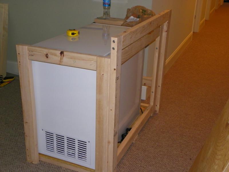
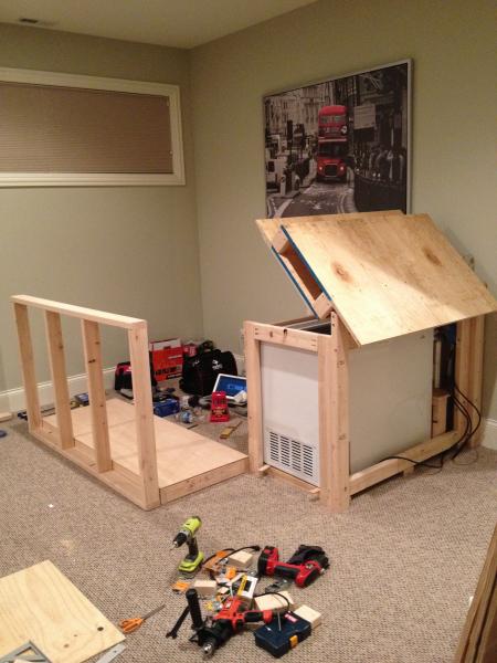
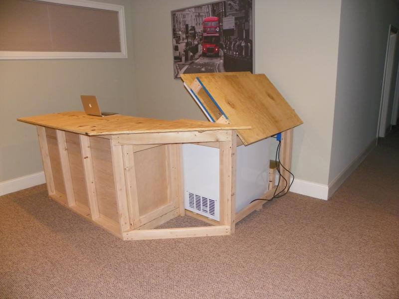
I originally began a thread based on the notion that I would be building a keezer. SWMBO asked why I wasn't just building a bar with the keezer built in. That's a great idea says I, hence this new thread. I'll plug in a few pics of how I started and where I am to date (not yet finished).

The bar itself is inspired by Cruelkix's bar and Jester369's keezer. Thanks guys for the ideas.

I am using Google Sketchup for the design work. It is easy to learn and provides a quick source of dimensional information if you have a laptop handy.

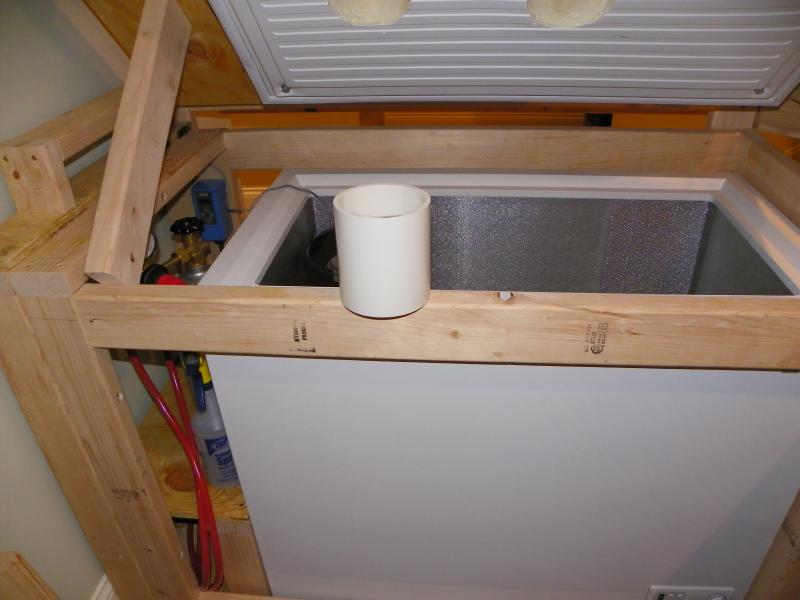
You will note that I elected to locate the CO2 tank and gauges outside of the keezer on a small side shelf (another idea found on this forum).

Pocket screws are used on the lower back member to allow for removal of the freezer in the future if necessary.

Stay tuned for how I incorporate the coffin. I am leaving the coffin as the last framing element since it is easier to square and true everything up and then add the coffin structure.

Dave.

103_1007.jpg


103_1009.jpg


IMG_0229.jpg


IMG_0232.jpg


IMG_0233.jpg
 
Thanks for the positive comments. More progress photos...

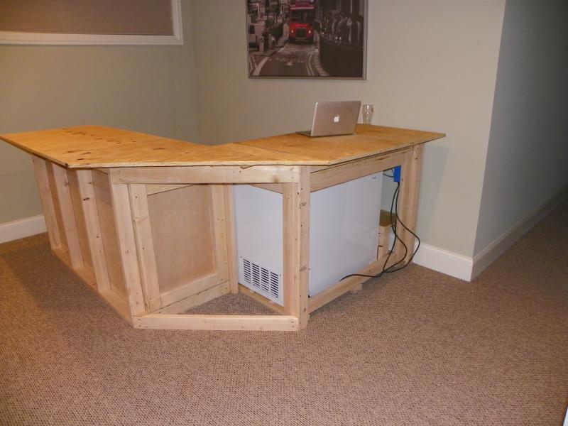
The main framing is finished. At some point there will be a big debate about materials for the top. Our home is fitted out with ebony stained oak, so the plan is to clad the framing with...you guessed it...very dark stained oak. Some nice LED lighting will work very nicely to accent.

The storage areas below on the non-keezer side are for glasses, shelving and a wine rack. And, since the compressor shelf is free, the missus gets to have wine chilling. (Small price to pay)

I should have time tomorrow to upload some staged pics of the most important part. I should be able to show some detail on how I plan to keep the coffin cooled. (This is where Jester369's influence comes into play)

~Dave

IMG_0234.jpg


103_1011.jpg


103_1014.jpg


103_1016.jpg


103_1017.jpg
 
Looking sharp. I built my bar a few years ago now and wish I would have had the foresight to think about the day the freezer is going to die. Gonna be a bit of fun ripping it apart to get at mine.

Knock on wood that won't be for a bit longer!
 
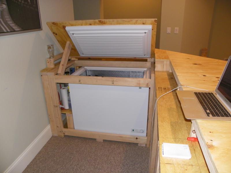
I started on the coffin part of the bar; pictures below.

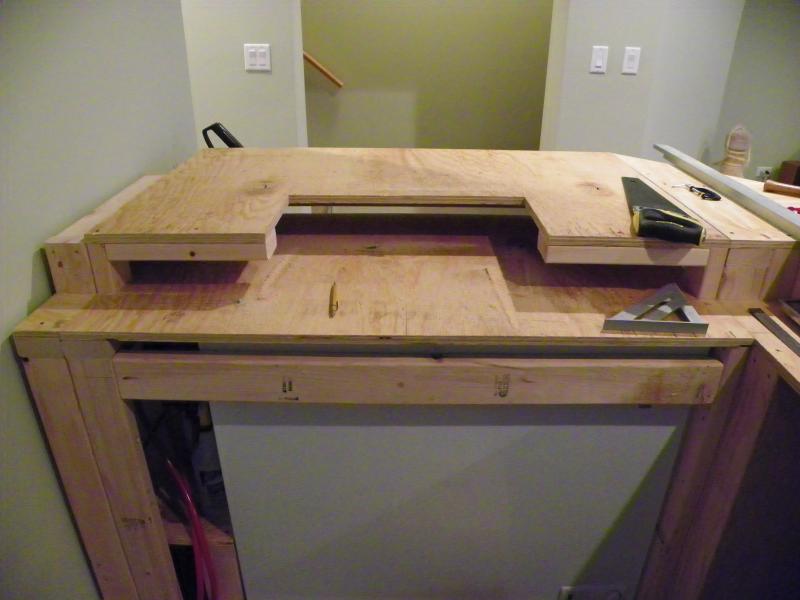
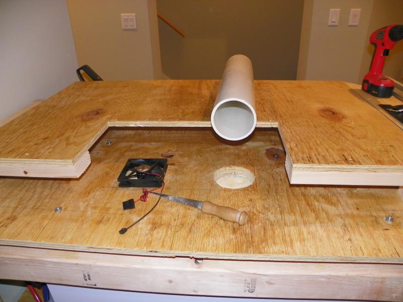
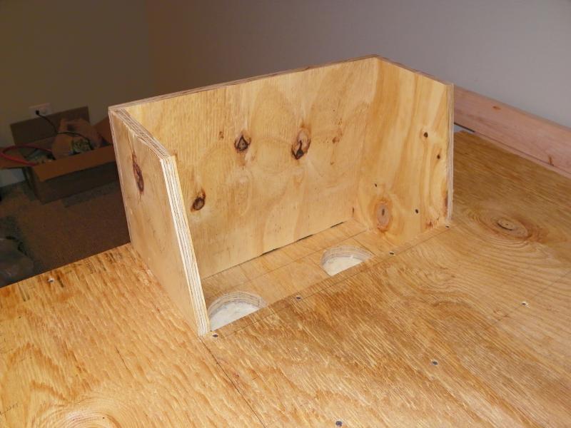
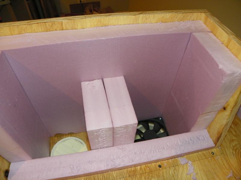
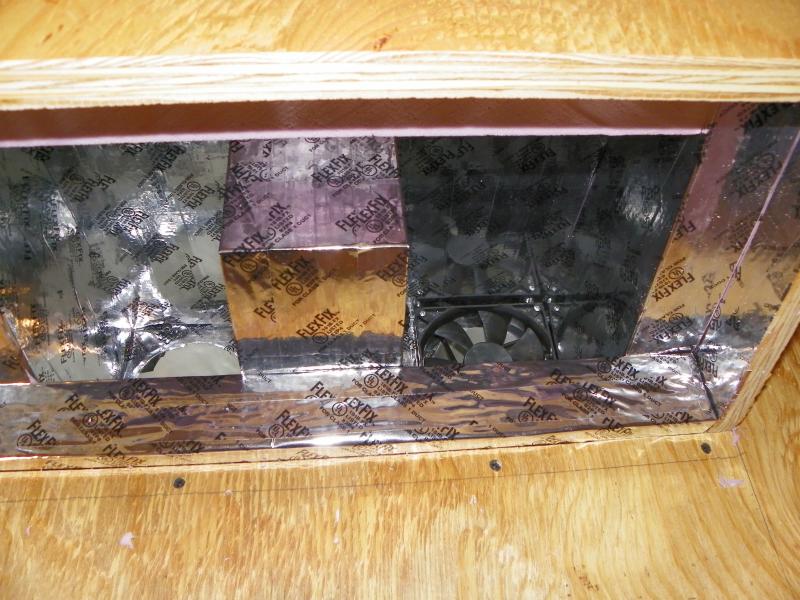
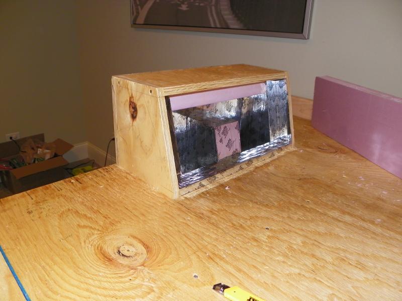
So, the main idea behind cooling the coffin is to use a fan to create a negative pressure on one side of the coffin box by blowing air from the box down into the freezer. The low pressure on the fan side of the coffin will pull air across a channel (constructed out of insulation foam) and up through another hole on the other side of the coffin (the pics will make things clearer). The beer lines will be fed up and routed through the high pressure side of the coffin thereby, in theory, cooling the lines and the exposed shanks as the air flows across and back down into the freezer.

I was going to use some flexible dryer duct hose to pull cold air from the bottom but on testing the setup tonight, I get plenty of cold air blasting up through the high pressure side.

It was a bugger cutting the holes through the sub-top down through the freezer lid but they turned out ok. My fan is a 120mm Antec computer fan with 3-speeds. 4 inch, Schedule 40 PVC pipe is the perfect size for this fan.

The pink foam is rough cut at the moment. I will go back behind, seal all the inside joints and cover surfaces with silver ductwork tape just to add another layer of help in keeping the cold in and the hot out.

Tomorrow night, I'll make the top of the coffin, cut the shank holes and start work on a removable back cover.

~Dave

103_1019.jpg


103_1023.jpg


103_1029.jpg


103_1038.jpg


103_1042.jpg
 
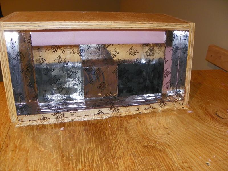
I apologise for not having updated for a while. Too many other irons in the fire. I've made a lot of progress and will plug in a bunch more pics to share the design. The coffin is working GREAT! No significant temperature differential from the fridge. I'll talk in more detail in the next post. For now, pics of the coffin construction are below.

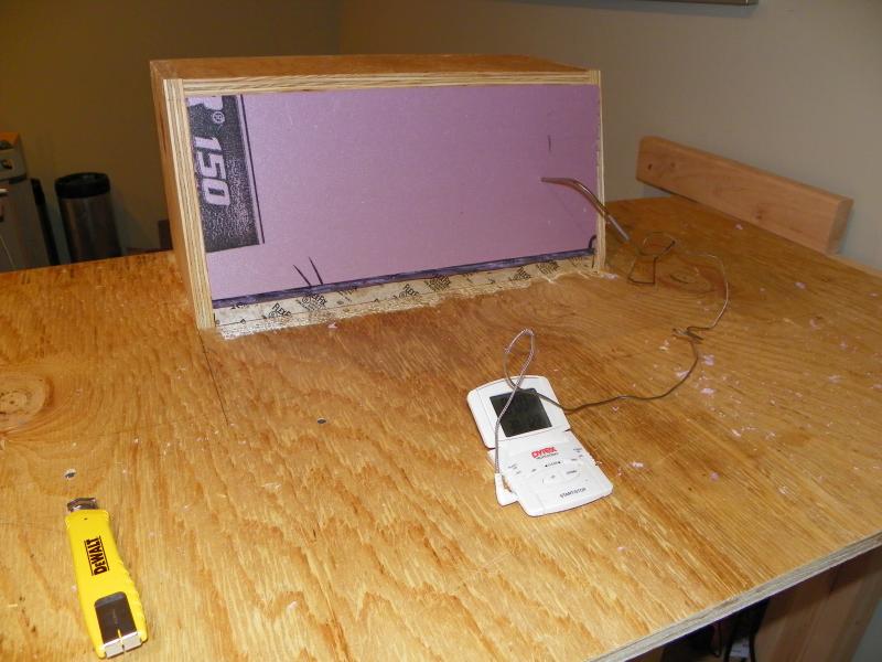
The R10 pink foam I used was easy to cut and, I think is just the right amount of insulation. I did take the extra step, as you can see, to tape everything with reflective tape - both sides. The idea is to reflect heat out and keep cold in.

I applied a temporary foam back to test the fan system and see what kind of temperature I could achieve. For the test, I set the freezer temp to 38 degrees the idea being that if I could get the coffin below 40 degrees, I'd call it good. Well, as you can see, the temperature in the coffin settled in at the same temperature as the keezer cabin. Nice! Mission accomplished. After that test, I taped everything up and moved on to installing shanks and taps...next post

Cheers,

Dave

103_1044.jpg


103_1043.jpg


103_1045.jpg


103_1047.jpg


103_1048.jpg
 
The next order of business with this build was to get the business end up and running. I want taps and flowing beer!!!

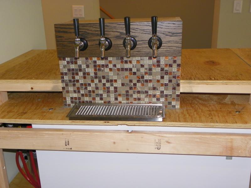
The first pic shows what the missus chose as a tile for the back splash (I have to say, she's got a good eye!). I stained a piece of oak using ebony stain and satin poly finish. The Perlick 575 creamer taps are installed.
The tile was super easy to work with since the small pieces are 1/2 inch which means that it can be cut very easily to the appropriate size. I got lucky in that the grid size fitted my backsplash area perfectly. If you do something similar, plan ahead.

In the next pic, you can see I decided to give the coffin it's own temperature control. This was because I wanted to maintain some consistency in temperature.

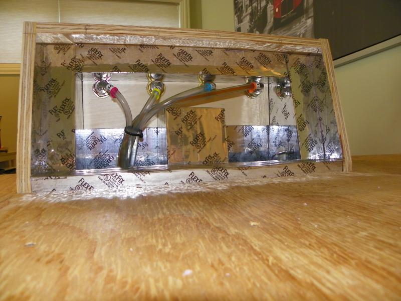
In the third pic, I've hooked up all the beer lines and, after hooking up a keg filled with Starsan to clean the lines, the first official keg is hooked up and flowing.

Note that inside the coffin box I have installed a 1/4" thick poplar board that allows me to tighten the shank nuts without crushing the foam insulation. On the right, you can see the temperature probe for the temperature controller. I also took the time to number and colour code the beer lines so I know what's what and where.

The drip tray has a drain line that I ran through the freezer lid and into a bottle that sits on compressor shelf.

103_1049.jpg


103_1052.jpg


103_1054.jpg
 
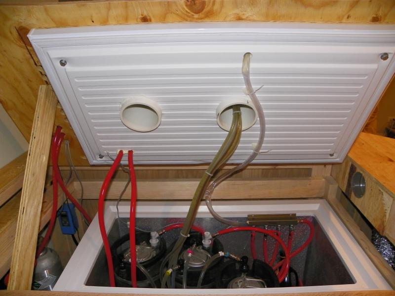
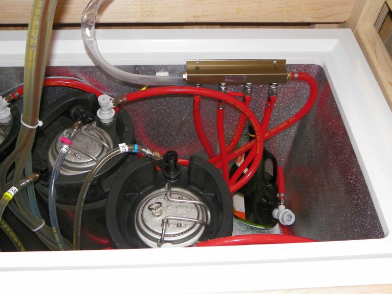
I used Oetiker clamps all around. They are extremely easy to install and make a leak free connection. They're much easier than buggering around with screw clamps although if you mess up, you sacrifice a clamp. The pics that follow show the routing of CO2 lines through the lid. In my set up, I have dual regulators so that I can run a higher carbonation pressure on one and serving pressure on the other. The serving pressure regulator feeds the 4-way valve manifold that is mounted on the right hand side above the compressor hump.

You can also see the drain line from the drip tray and the spill bottle sitting on the hump.

The observant will see that I've been busy doing the important stuff...brewing!! The three kegs hold a black IPA, an APA and a Dusseldorf Altbier.

I've taken care to bundle the beer lines as they feed through the high pressure coffin inlet so that air flow disruption is minimized.

103_1067.jpg


103_1066.jpg


103_1068.jpg
 
One of the things I was thoughtful about in the design process was how to effectively vent heat from the freezer outside skin since, as others have rightly pointed out, it can get rather warm when the compressor is on.

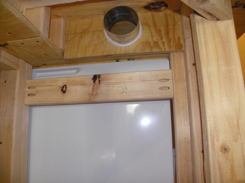
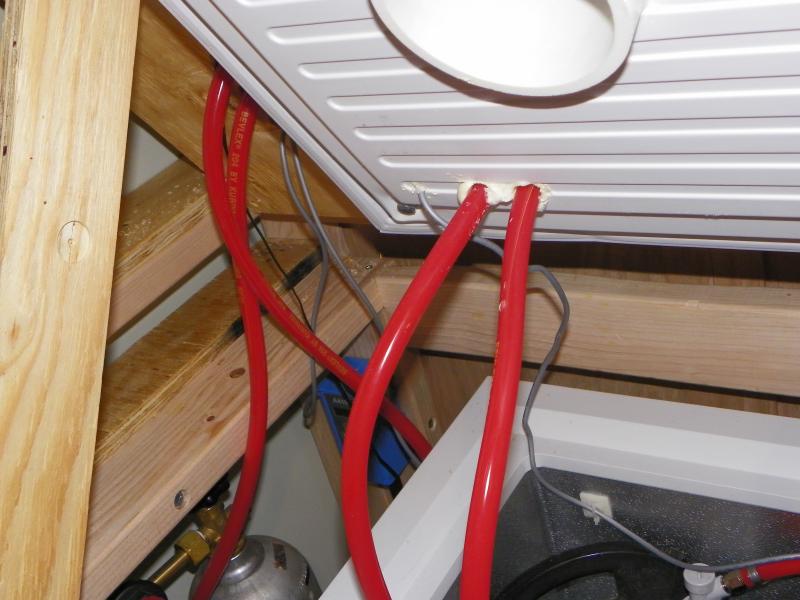
The upper, raised section of the bar top lends itself to becoming a very nice air plenum chamber. So, I decided to install an Inductor fan to pull air from the plenum and vent it in a hidden part of the bar.

To obtain a good flow of cool air across the freezer outer skin, I wanted to use some convection in addition to pulling the air with the fan. The idea is that air is pulled from ground level (cool), up over the skin of the freezer, then through a series of holes into the plenum chamber before being evacuated by the inductor fan. Below are some pics to illustrate...

The air exhausts into the angled corner section of the bar where I use flexible duct to connect the Inductor fan and then terminate the duct in one of the shelf sections.

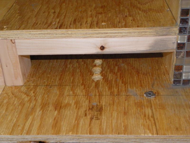
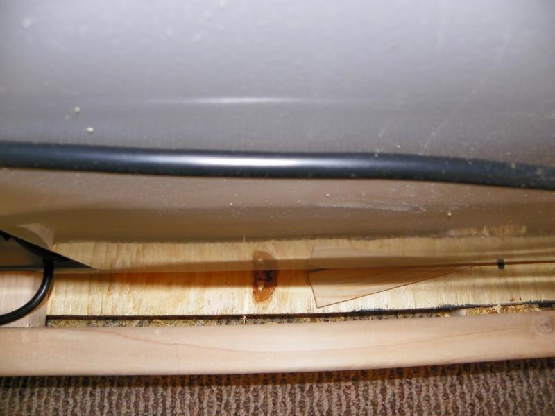
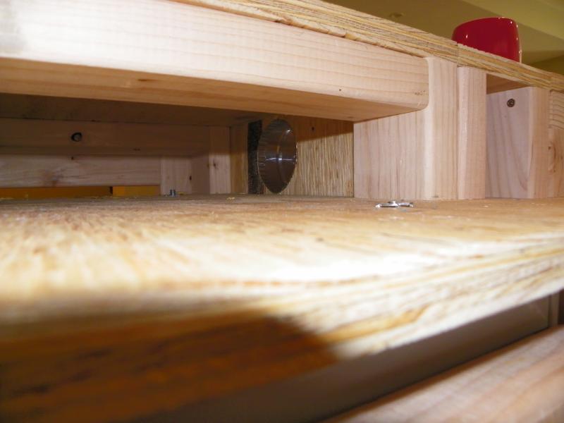
The third pic shows the air gap that I left between the freezer base and the structural two-by's to allow air flow from the bottom up.

The fourth pic is a view looking from the tap side of the top before I enclose it with trim to complete the plenum sealing.

103_1056.jpg


103_1057.jpg


103_1058.jpg


103_1060.jpg


103_1062.jpg
 
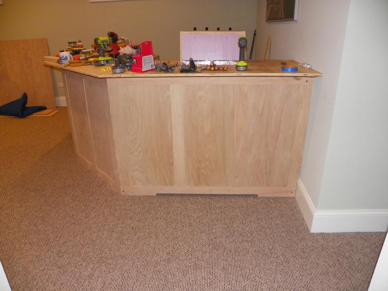
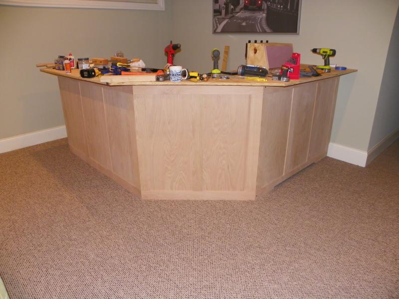
Here are some pics of the external decorative work of the bar. The first shows the basic panel arrangement. I used biscuit joinery to simplify things. The materials are 3/4" oak for the rails and stiles with 1/4" oak plywood for the panel.

In the other pics you will notice a cut out at the bottom to allow air to flow up and across the freezer skin into the plenum. Both the back and front panels for the freezer section are removable and secured with decorative screws.

Also, you might notice a bit of anal attention to detail, where the stiles that butt up to the skirting board (base board in US speak) have been coped to fit the profile of the skirting. Not a bad fit if I say so myself!

I'll post some more pics next week when I get some more time to play with the trim work.

Cheers!

Dave

103_1050.jpg


103_1063.jpg


103_1064.jpg


103_1065.jpg
 
Thanks for the compliment!

I will try to take a clearer photograph later this week but, for now, let's take another look at the pic below...

I'm hoping that you can see from the pic that the CO2 tank is stored on a shelf that I made that is outside of the freezer. BTW here's a tip that I found on one of the Keezer threads...a one gallon paint can makes the perfect "sleeve" for the diameter of a 5# tank. I didn't even screw it down. The cross-sectional area is enough that the tank, even with the overhung load of the regulators and gauges, is quite stable and doesn't topple easily.

So, back to the CO2 line routing...There are two holes that need to be drilled: one outside of the freezer lid and one THROUGH the freezer lid. The line is fed from the regulator UP through the outside hole and then looped DOWN through the lid hole and into the freezer compartment. When I was cutting to length and clamping the CO2 lines, I made certain to leave enough slack in the lines to allow for opening the lid while not having so much that the lines would get caught under the lid when it is closed. Make sense?

Just to be totally clear: in the pic you can see TWO lines going up and then down. One is the higher pressure carbonation line, the other is the line that feeds the 4-way manifold.

Hope this helps. I'll clarify with later this week with another pic.

Dave

103_1067.jpg
 
Ahh much more sense now. The two lines going in confused me.

My keezer holds 6 kegs but i only want 4 taps (for now). Great idea splitting off the two lines for two different tasks. Do you have 2 different regulators?

Thanks
perogi.
 
Hi. I'm really impressed with this. I admire your knowledge, where-with-all, creativity and execution. Would you mind if I refer others to it or use any of your pictures on my site? I help others in planning, designing and executing when learning how to build a bar. I'm going to see what other threads you have, and would welcome your input.

Thanks a lot for a great, informative post.

:mug:
 
How-To-Build-A-Bar said:
Hi. I'm really impressed with this. I admire your knowledge, where-with-all, creativity and execution. Would you mind if I refer others to it or use any of your pictures on my site? I help others in planning, designing and executing when learning how to build a bar. I'm going to see what other threads you have, and would welcome your input.

Thanks a lot for a great, informative post.

:mug:

No problem with directing others here and thanks for the compliments. HomeBrewTalks is the perfect forum for sharing and learning. I'm happy to help out and answer any questions.

Dave
 
Great Build!

What size freezer do you have there and if you don't mind my asking, do you still have the Sketchup files handy?
 
Very nice! Did you remove the hinges from the freezer and just bolt the lid to the plywood top? What type of hinges did then use to open and close it? Really nice design!
 
cjwu40 said:
Great Build!

What size freezer do you have there and if you don't mind my asking, do you still have the Sketchup files handy?

The freezer is a GE 7 cu ft model that I bought from Home Depot. It fits four corny kegs snugly. I will dig out the Sketchup file and send to you.

Dave
 
sredz said:
Very nice! Did you remove the hinges from the freezer and just bolt the lid to the plywood top? What type of hinges did then use to open and close it? Really nice design!

Yes, the original hinges were removed from the freezer. The freezer lid is bolted to the subtop plywood. I installed T-nuts in the plywood and then bolted from inside the freezer. Take a look at the earlier photos and you will see the bolts in the underside corners of the lid.

The bar top is hinged using a four foot long piano hinge. I'll see if I can take a photo that clearly shows the piano hinge placement.
 
Ok, fellas, once again I apologise for the delayed update. Things took a bit longer than planned mainly due to the fact that once the beer was flowing, it became a bit dangerous to mix power tools with strong beer. But...the bar is now all but finished. In the next few posts I'm going to post a bunch of pics that show how things progressed with the top surface and the final finishing. I'll throw in some commentary in places when I think it might be helpful but please don't hesitate to ask for clarification.
 
Photos show that I had installed the finishing trim oak to cover all of the plywood surfaces. I purchased solid red oak bar edge from Hardwoods Incorporated. Their site has a great information that shows the dimensions and required arrangements of the top and sub-top wood. There is also an awesome video showing how to properly install the bar edge.

The last picture shows me applying stain to the skirt panels. It also shows some elements of what I was originally going to use to "fill" the top surface of the bar. You will see later that I ended up using tongue-and-groove solid oak wood flooring.

photo (1).jpg


103_1088.jpg


103_1092.jpg


103_1093.jpg
 
The first picture shows how I used the tongue-and-groove boards to diagonally fill the area bordered by the oak trim. Some construction details:

  • No glue is used; I want the fill to move a little if it needs to.
  • The boards are laid in with the tongue facing towards me. That allows me to use my nail gun to shoot a nail down at an angle down and through the tongue into the sub-surface plywood. If you get the angle right, the nail should not interfere with the mating groove of the next piece.
  • The joinery gets a bit tricky at the corners. Patience is a must but the reward is big.

The final pic shows progress of the staining. You can see the removable inside skirt leaning against the wall on the left.

Dave

103_1095.jpg


103_1096.jpg


103_1097.jpg
 
In these two photos I have finished the oak fill for the fixed top. I had to do some hand planing to even up thickness differences between the tongue-and-groove fill and the outside trim. I sanded with progressively finer sand paper starting with 60 grit and progressing through 80, 100, 120, 150, 180 and 220. Yes, this is a lot of sanding but, believe me, the effort is worth the final result.

Next step was to apply stain. You might notice that there are some visible nail holes on the external trim work (bottom left of first pic). This is a trick I learned a long time ago: don't fill nail holes until after the first coat of varnish/urethane/whatever; this prevent oils from the nail hole filler from leaching into the surrounding wood and messing up the look of the stain.

IMG_2404.jpg


IMG_2398.jpg
 

Latest posts

Back
Top