
I'm trying to wire up a BrewPi to use with Fermentrack using this wiring diagram from 100amp: Native ESP8266 BrewPi Firmware - WiFi BrewPi, no Arduino needed!.
I'm running into an issue where it appears that the heating and cooling relays won't open. When I set the beer constant in Fermentrack to 80F, the program will call for heat, and the blue LED on the 2-channel lights up, but bupkis from the heater. The heater, in this case, is a 75W reptile bulb. The bulb is turned on, and works fine with an Inkbird 308, so that's not the issue. I've tried setting both heating and cooling to 'not inverted', per another thread. When I do, LEDs on both sides of the relays light up, but no heating or cooling occurs. I've tried resetting EEPROM and the ESP8266 without success. Given that the LEDs on the relay and AC - DC converter both light up, and the ESP8266 turns on and works, it has to be a problem on the AC side, right?
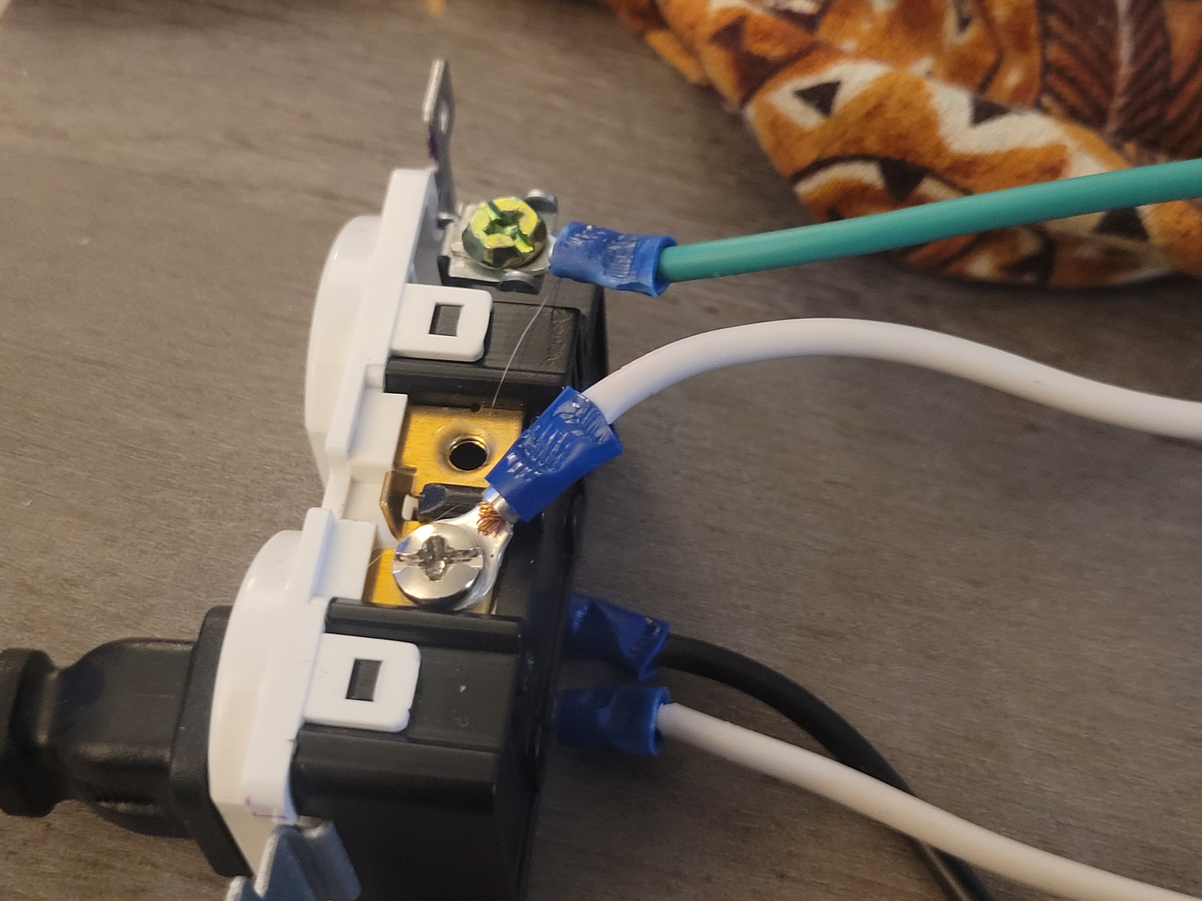
Attached are 4 photos of the AC side of the wiring. As far as I can tell, this should work, but it isn't. Am I doing something wrong here?
If it's not the AC wiring, any other suggestions of what it might be?
I'm running into an issue where it appears that the heating and cooling relays won't open. When I set the beer constant in Fermentrack to 80F, the program will call for heat, and the blue LED on the 2-channel lights up, but bupkis from the heater. The heater, in this case, is a 75W reptile bulb. The bulb is turned on, and works fine with an Inkbird 308, so that's not the issue. I've tried setting both heating and cooling to 'not inverted', per another thread. When I do, LEDs on both sides of the relays light up, but no heating or cooling occurs. I've tried resetting EEPROM and the ESP8266 without success. Given that the LEDs on the relay and AC - DC converter both light up, and the ESP8266 turns on and works, it has to be a problem on the AC side, right?
Attached are 4 photos of the AC side of the wiring. As far as I can tell, this should work, but it isn't. Am I doing something wrong here?
If it's not the AC wiring, any other suggestions of what it might be?


![Craft A Brew - Safale S-04 Dry Yeast - Fermentis - English Ale Dry Yeast - For English and American Ales and Hard Apple Ciders - Ingredients for Home Brewing - Beer Making Supplies - [1 Pack]](https://m.media-amazon.com/images/I/41fVGNh6JfL._SL500_.jpg)


