• Please visit and share your knowledge at our sister communities:
  • If you have not, please join our official Homebrewing Facebook Group!

    Homebrewing Facebook Group

Help with brew system

Homebrew Talk

Help Support Homebrew Talk:

This site may earn a commission from merchant affiliate links, including eBay, Amazon, and others.

Redpappy

Well-Known Member
Joined
Nov 5, 2017
Messages
784
Reaction score
316
Location
Mt orab
hello all. I am needing some help. I plan on a simple brew system. After much thought this is what I am planning. A 5 gal electric BIAB system. I think I have the kettle figured out, but not sure on the control system. I know this will take me a few years to build, so I figured I would start with the kettle. I am looking into getting a Spike Kettle, with all the ports drilled, and caps installed for the time being. ( 3 ports in front, 2 on the bottom and one on top) and 2 ports in back ( 1 for the element and one for temp). I am having all but 1 hole plugged for now, since i will be brewing with propane for now. From there I have no idea where to go. I do plan on using a 240V 30 amp circuit. ( I will be in a basement) I am thinking of doing a 5500 watt element.

I am looking at the 10gal kettle, I mainly brew small batches (1060 OG or lower) I am planning to keep my system as simple as possible.

Any suggestions, thoughts, are welcome and appreciated
 
It's not too hard to build your own kettle element controller if you are comfortable working with electrical stuff (or know someone that is who can help you.) There are many ways to put together a controller that will do the job, depending on the functionality you desire, and your sense of aesthetics. Here are a few designs I have done for BIAB systems.

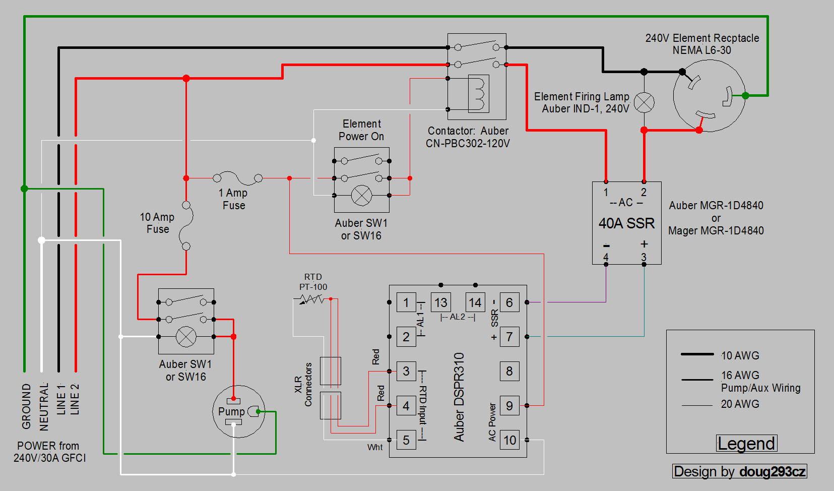
The first uses the Auber EZBoil DSPR310 which allows automated step mashing as well as an external alarm buzzer/light (louder than the internal alarms in EZBoils.) If you don't want the step mashing functionality, you can use the DSPR300 instead of the 310. And, if you don't care about loud alarms, you can use the DSPR120.

DSPR310 1-Pump 240V.PNG


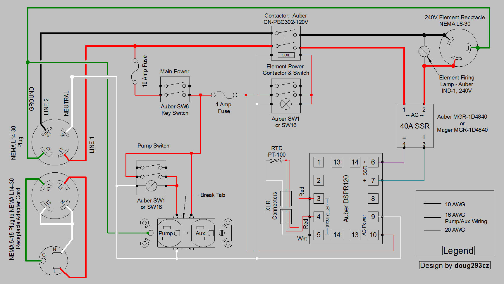
Here's another design that uses the DSPR120 (no automated step mashing, or external alarms.) The two connector "pigtail" in the lower left is optional, and allows the system to be used on a 120V supply (but at 1375W max.)

DSPR120 1-Pump 1-Aux Dual Voltage Input contactor.PNG


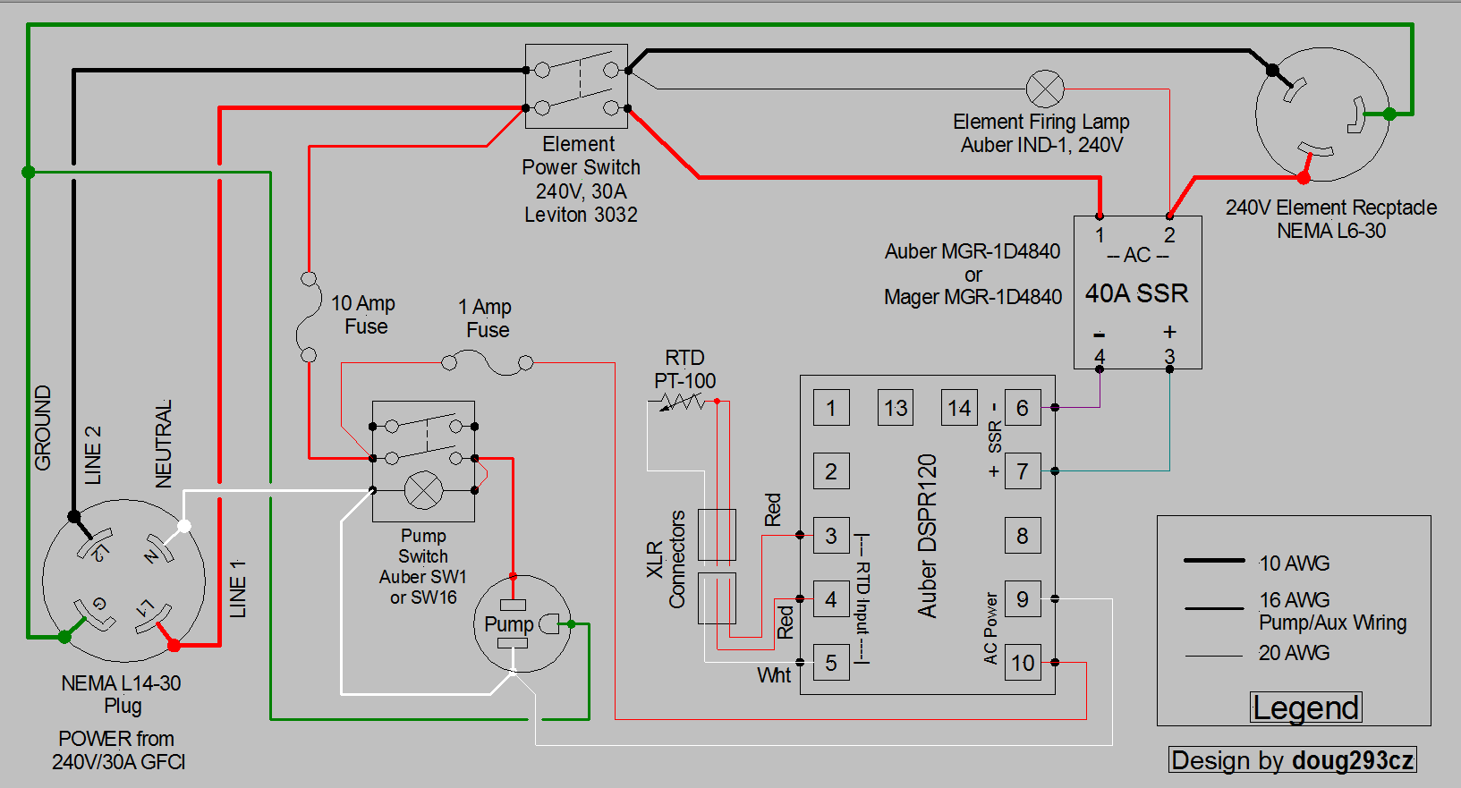
This one's about as simple as you can get, and still have the pump controlled by the same panel.

DSPR120 1-Pump Simple.PNG


If you have questions, or are looking for something a little different, just ask.

Brew on :mug:
 
Thanks doug293cz. The last one is pretty much what I am looking for. Is there any specific style of fuse holder that you would suggest?
 
Thanks doug293cz. The last one is pretty much what I am looking for. Is there any specific style of fuse holder that you would suggest?
I'm partial to the panel mount fuse holders, but anything that you think will be easy to mount will work.

The Leviton switch specified is basically a high power wall style "light" switch. The aesthetics aren't great, but many brewers use them with success. Also, be aware that with that design, the DSPR will come on as soon as the panel is plugged in. It's very low power, so that is not a problem.

Brew on :mug:
 
Last edited by a moderator:
I would use a double pole SSR when using 220V that switches both hots. Switching one leaves the other one hot which can still be putting out 120v if there is a problem with the SSR. You already have a double pole switch, this is a simple modification.
 
I would use a double pole SSR when using 220V that switches both hots. Switching one leaves the other one hot which can still be putting out 120v if there is a problem with the SSR. You already have a double pole switch, this is a simple modification.
I disagree, as this will double the switching losses due to the SSR, and none of the sellers of electric brew systems (of which I am aware) switch both hots with SSR's. The SSR is only for the rapid switching needed for power control. It is not meant to be, and is not safe to use as a positive disconnect. The power disconnect does need to be double pole, and is either handled by a high current mechanical switch, or an electromagnetic contactor. All of my designs include such a double pole, positive disconnect for the main power.

Brew on :mug:
 
It's not too hard to build your own kettle element controller if you are comfortable working with electrical stuff (or know someone that is who can help you.) There are many ways to put together a controller that will do the job, depending on the functionality you desire, and your sense of aesthetics. Here are a few designs I have done for BIAB systems.

The first uses the Auber EZBoil DSPR310 which allows automated step mashing as well as an external alarm buzzer/light (louder than the internal alarms in EZBoils.) If you don't want the step mashing functionality, you can use the DSPR300 instead of the 310. And, if you don't care about loud alarms, you can use the DSPR120.

View attachment 561338

Here's another design that uses the DSPR120 (no automated step mashing, or external alarms.) The two connector "pigtail" in the lower left is optional, and allows the system to be used on a 120V supply (but at 1375W max.)

View attachment 561345

This one's about as simple as you can get, and still have the pump controlled by the same panel.

View attachment 561344

If you have questions, or are looking for something a little different, just ask.

Brew on :mug:

These are awesome. I'm planning a move to a recirculating eBIAB and the top design looks like what I'm wanting. I have a few questions:

The items needing cutouts on the front of the panel would be:
The DSPR310
The two SW16's
The IND-1 firing lamp

Then the bottom (or back if a tabletop approach) would need cutouts for:
XLR Temp connectors (why two?)
NEMA L6-30 Receptacle
standard 120v receptacle for the pump
Power in receptacle or strain relief if hard wired

Am I missing anything? Any advice for layout (both internal and external)?

The SW16's come in two NO or 1 NO and 1 NC configurations. Looking at the diagram, I'm assuming the 2 NO configuration?

The part numbers for the 40A SSR don't show up on Auber's site. Is this one acceptable?

Any other advice? I built a guitar amp about 10 years ago, but for that I had a wiring diagram and a drawing of the layout (where to route the wires, etc.). This shows the connections, but is pretty much a blank slate for how to lay it out.
 
hello all. I am needing some help. I plan on a simple brew system. After much thought this is what I am planning. A 5 gal electric BIAB system. I think I have the kettle figured out, but not sure on the control system. I know this will take me a few years to build, so I figured I would start with the kettle. I am looking into getting a Spike Kettle, with all the ports drilled, and caps installed for the time being. ( 3 ports in front, 2 on the bottom and one on top) and 2 ports in back ( 1 for the element and one for temp). I am having all but 1 hole plugged for now, since i will be brewing with propane for now. From there I have no idea where to go. I do plan on using a 240V 30 amp circuit. ( I will be in a basement) I am thinking of doing a 5500 watt element.

I am looking at the 10gal kettle, I mainly brew small batches (1060 OG or lower) I am planning to keep my system as simple as possible.

Any suggestions, thoughts, are welcome and appreciated

BTW....I just exchanged emails with spike on Friday asking about eBIAB systems. I suggested it would not be a leap for them to do a turnkey system. They don't plan to, but they do have an eBIAB kettle plan that looks a lot like you describe. I'll post it when I can.
 
BTW....I just exchanged emails with spike on Friday asking about eBIAB systems. I suggested it would not be a leap for them to do a turnkey system. They don't plan to, but they do have an eBIAB kettle plan that looks a lot like you describe. I'll post it when I can.
. I was in talks with them a week ago. It started off by me inquiring on if the temp probe would snag a bag if I had it in the lower port on their side by side. I also explained what my future plans were, and the response was the BIAB brew kettle. It took a few days inquiring about what all the ports was for. I am expecting my kettle in 2 weeks or so....
 
. I was in talks with them a week ago. It started off by me inquiring on if the temp probe would snag a bag if I had it in the lower port on their side by side. I also explained what my future plans were, and the response was the BIAB brew kettle. It took a few days inquiring about what all the ports was for. I am expecting my kettle in 2 weeks or so....

I was curious what the intended use for each port was. It seemed like an element port, temp port, drain port, regular temp gauge and recirculation return port.
 
These are awesome. I'm planning a move to a recirculating eBIAB and the top design looks like what I'm wanting. I have a few questions:

The items needing cutouts on the front of the panel would be:
The DSPR310
The two SW16's
The IND-1 firing lamp
Also, the SW8 key switch

Then the bottom (or back if a tabletop approach) would need cutouts for:
XLR Temp connectors (why two?) Not two connectors, but rather one connector pair (plug and receptacle)
NEMA L6-30 Receptacle There is an option here. You can put the receptacle in the enclosure, or if you have an element with an integral L6-30 plug, you can use a strain relief at the panel and an L6-30 receptacle on the element end of the cord.
standard 120v receptacle for the pump
Power in receptacle or strain relief if hard wired Power input must always be a plug (male - receptacles are always female), otherwise the power cord would have exposed plug blades at the panel end, which is a HUGE safety hazard, and a code no-no. If you use a strain relief at the panel, then the other end of the cord must have a plug for a wall socket. Code won't let you hard wire the panel to your electrical service (cause your home built panel, by definition, is not code compliant.)

Am I missing anything? Any advice for layout (both internal and external)? Layout depends to a great extent on the actual enclosure you choose. Too, many possible options for me to make specific recommendations on interior layout. I do suggest you mock everything up for fit before you start cutting any holes.

For SSR/heatsink mounting, I recommend mounting the heatsink on the side of the enclosure (based on the orientation the enclosure will have during use) with the heatsink fins oriented to allow maximum vertical airflow. The hole in the enclosure should be slightly larger than the base of the SSR, so that the SSR can mount directly to the heatsink (with a little thermal grease in between), and the heatsink attached to the enclosure wall.

The SW16's come in two NO or 1 NO and 1 NC configurations. Looking at the diagram, I'm assuming the 2 NO configuration? You can use either the 2-NO or 1-NC/1-NO, since you are only using one of the switch blocks (NO) in this design. However, by using the 1-NO/1-NC version, you have the option to add a "safe start" power interlock later, if you so choose. 2-NO is best for the SW8.

The part numbers for the 40A SSR don't show up on Auber's site. Is this one acceptable? That is the MGR-DS4840, Auber just calls it something else on their catalog page (note that they use of picture of the 25A MGR-DS4825 on that page - sloppy editing.)

Any other advice? I built a guitar amp about 10 years ago, but for that I had a wiring diagram and a drawing of the layout (where to route the wires, etc.). This shows the connections, but is pretty much a blank slate for how to lay it out.

Let me know if you have any other questions.

Brew on :mug:
 
I was curious what the intended use for each port was. It seemed like an element port, temp port, drain port, regular temp gauge and recirculation return port.
When I asked them, they stated “ re-circulation port ton top front, bottom drain port and whirl pool, back bottom is for temp probe and element.
 
Here’s a question for you doug293cz. Do you see an issue with adding another single outlet and switch to your bottom plan. This is what I was thinking, tie a third hot (red) wire to the power switch, attach 10 amp fuse, to a sw1, then to a single outlet. Running a piggy back neutral wire from 1 st switch to second, and moving the neutral wire for the dspr120 to the second outlet. I may have 2 pumps running at the same time, but will not have the element on, so I know I’m good with the volts and amps, but not sure if attaching a third wire to the switch is wise.

Reason for second switch is to run a pump for my immersion chiller. Right now I have a pump that circulates water from a tub through my chiller. I have the pump mounted and tied into a switch already. But I plan on having it on the ground and would like to get away from having to bend over to turn it on and off.

On the layout, would you keep the plugs ( the 240) location the the door or would you tie them on the sides of the box? The box that I am considering has a hole for a heatsink and ssr location on top, would that creat an issue?

Thanks for all the help and advise. A little bit of my back ground...
This is my first build on electronics. scary I know. I do have some knowledge on electric, and have done some house hold electric work, ie, re-wiring a room, running a line for a stove. And I will be attempting to make my own stir plate in a week or so. As soon as I get an old pc to rip into.
 
Receptacles and plugs should go on the sides or bottom of the enclosure.

Yes you can definitely add another switch and outlet, wired similar to the existing switch outlet. Doesn't really matter if you tie to the red hot line or the black hot line (although the black would balance out your phase amps when both pumps are running.

People routinely mount heatsinks on the top of the enclosure. It's not quite as good thermally as on the side, but usually works fine, if everything else about the SSR/HS mounting is done correctly.

Brew on :mug:
 
Back
Top