Help - I'd like to use a Solid State Variable Relay in a P-J BIAB circuit

Homebrew Talk - Beer, Wine, Mead, & Cider Brewing Discussion Forum

Help Support Homebrew Talk - Beer, Wine, Mead, & Cider Brewing Discussion Forum:

This site may earn a commission from merchant affiliate links, including eBay, Amazon, and others.

time2brew

Active Member
Joined
Oct 30, 2011
Messages
41
Reaction score
7
I've admired P-J's work for some time now and I'd like to make the eBIAB plunge albeit with a slight twist. I'd like to use a Auber PID (SSR or Relay output?) to control a "Solid State Variable Relay" (SSVR) like the one from this post https://www.homebrewtalk.com/f170/variable-resistance-ssr-boil-control-310622/. I realize that the Auber PID can be placed into manual mode to provide the same level of adjustment but I like the simplicity of just twisting a knob for fine control.

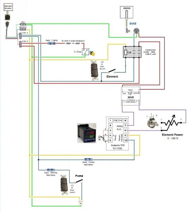
I'm trying to figure out how to modify a circuit like P-J's "Auberin-wiring1-a4-5500w-BIAB-30d12" drawing to accommodate the SSVR.

Ideally, I'd like to set the SSVR @ 100%, program the PID for my mash temp, complete the mash, re-program the PID to boil temp & use the SSVR knob for fine control of the boil.

Has anyone used one of these SSVR SSR's in their e-brewery?

Thanks
 
what I would do is connect it up after the contactor to controll the boil
 
I've admired P-J's work for some time now and I'd like to make the eBIAB plunge albeit with a slight twist. I'd like to use a Auber PID (SSR or Relay output?) to control a "Solid State Variable Relay" (SSVR) like the one from this post https://www.homebrewtalk.com/f170/variable-resistance-ssr-boil-control-310622/. I realize that the Auber PID can be placed into manual mode to provide the same level of adjustment but I like the simplicity of just twisting a knob for fine control.

I'm trying to figure out how to modify a circuit like P-J's "Auberin-wiring1-a4-5500w-BIAB-30d12" drawing to accommodate the SSVR.

Ideally, I'd like to set the SSVR @ 100%, program the PID for my mash temp, complete the mash, re-program the PID to boil temp & use the SSVR knob for fine control of the boil.

Has anyone used one of these SSVR SSR's in their e-brewery?

Thanks

I use one to control my boil kettle and it works great. I started to go the AUBER route then I realized that setting the boil through the PID control panel was going to be more trouble than it's worth.

With a SSVR I start with the knob set full-on then I just turn down the heat when the boil starts. It's like gas heat, only better because there is never a flame-out and no hot gas exhaust blowing by the sides of the pot.
 
First off, I hope I don't offend anyone by my attempt at modifing one of P-J's (most excellent) drawings to allow the use of an SSVR.

I like the idea of using a knob to control the boil vs. a PID's manual-mode much like HighGravity's EBC SV with Infinite Power Control.

I think I'd need to use a PID with Relay output (2342?) and, based on the input I received, I'd need to move the SSVR between the contactor and element.

Would this allow the PID to drive the contactor for temperature controlled mashing?

The SSVR knob would be set to 100% for the mash and adjusted accordingly to control the boil.

Does this look like it would work as intended?

P-J_Auberin-wiring1-a4-5500w-BIAB-30d6 SSVRd8-1.jpg
 
Hmmmm - it depends on how the SSVR behaves with nothing connected to the control side. It is designed to see a particular resistance across the control terminals and behave a certain way based on that resistance.

Removing the potentiometer (by opening the PID relay) would leave both the control terminals floating and may make the SSVR behave unexpectedly.

I have considered this as well, so that I could fine tune the RIMS element power where rather than short on bursts of high power you could power it down for longer more even heating. (I've talked myself out of it though...) I decided the correct way to do it would be to add the SSVR in series with the normal SSR.

The PID would control the normal SSR as usual, then the SSVR would "throttle down the voltage" from the main SSR. Does that make sense?
 
The circuit won't work.

What you need is a normal SSR whose low voltage input can be switched between the PID and a PWM circuit with a manual control.
 
Huff360 and alien thanks for your input.

My SSVR arrived last night so I decided to conduct an actual test.

I pieced together the circuit in the attached diagram and plugged an electric lamp into the outlet.

I'm happy to say that it works exactly as I'd hoped. :ban:

Opening the "PID Relay" (I just removed the wire to SSVR pin-4) causes the SSVR to see infinite resistance which in turn shuts down the output and turned off the lamp.

Adjusting the potentiometer dial to the right causes the output to ramp up from 0% to 100% power.

Pulling the wire off of SSVR pin-4 turns off the output regardless of the dial setting and when the wire is reattached the output goes right back the the level set by the dial.

Test Circuit.png
 
After thinking about it a little - I think the best way to do this would be like this:

CCI10102013_0000.jpg

This would prevent the pins on the SSR from floating when the PID is off and assure you that the SSR is in the off state.

500 Ohm 2W resistor - $1.40
http://www.digikey.com/product-detail/en/42J500E/42J500E-ND/1124959


It's never a good idea to float a connection that is not intended to float.
 
Huff360 you make a great point.

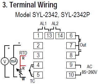
So I Looked more closely at the SYL-2342 Manual and see that it shows -

terminal 6 is the N.C. side of the relay
terminal 7 is the output of the relay
terminal 8 is the N.O. side of the relay

That being the case, I've tweaked the drawing to include a 500 K Ohm 2W resistor that comes into play when the relay isn't being energized.

SYL-2342 PID Wiring.JPG


P-J_Auberin-wiring1-a4-5500w-BIAB-30d6 SSVRd10.jpg
 
Huff360 you make a great point.

So I Looked more closely at the SYL-2342 Manual and see that it shows -

terminal 6 is the N.C. side of the relay
terminal 7 is the output of the relay
terminal 8 is the N.O. side of the relay

That being the case, I've tweaked the drawing to include a 500 K Ohm 2W resistor that comes into play when the relay isn't being energized.


This looks good.

One worry I have is that it is going to be difficult to tune the PID if you adjust the "power" knob. Say you autotune at 100% power, then tune down to 50% power later. I'm not sure how much authority the Fuzzy Logic has over the PID settings, you may not hold temps like you want with the reduced power.

This isn't a problem in the BK, but would be for the MLT if you didn't turn it back up to 100% power each time.
 
My fault, I didn't understand the first time around that this would connect to the PID relay output rather than the PID SSR output. :eek:
 
First off, I hope I don't offend anyone by my attempt at modifing one of P-J's (most excellent) drawings to allow the use of an SSVR.

I like the idea of using a knob to control the boil vs. a PID's manual-mode much like HighGravity's EBC SV with Infinite Power Control.

I think I'd need to use a PID with Relay output (2342?) and, based on the input I received, I'd need to move the SSVR between the contactor and element.

Would this allow the PID to drive the contactor for temperature controlled mashing?

The SSVR knob would be set to 100% for the mash and adjusted accordingly to control the boil.

Does this look like it would work as intended?

Time2brew, I saw a posting from you in the thread on PJ Diagrams and wondered if you had built your control panel. I searched your profile and found this thread. Chances are that you've already found the answer to your question.

If I'm understanding this correctly, you have the SSVR connected to the low voltage DC circuit from the PID to the SSR. I believe that you need to insert into one of the hot lines to the element - either the switched leg that goes thru the SSR or the other one.

This is not exactly how High Gravity does theirs, though, but it would emulate it exactly. We've been discussing this lately on a couple other threads regarding incorporating both SSR/PID and SSVR into the same controller.

See post #11 in the following thread:
https://www.homebrewtalk.com/f170/infinate-power-control-453592/index2.html#post5822761

Here's the diagram by Dawaii referenced in that thread:

137544d1374872203-potentiometer-ssrv-wiring-help-


and post #8 of the following thread:
https://www.homebrewtalk.com/f170/upgrade-ssvr-pid-ssvr-452510/#post5811944

So, the short answer would be that you would insert the SSVR and its potentiometer into one of PJ's diagrams after the SSR.

Thanks,
Keith
 
After thinking about it a little - I think the best way to do this would be like this:

View attachment 153100

This would prevent the pins on the SSR from floating when the PID is off and assure you that the SSR is in the off state.

500 Ohm 2W resistor - $1.40
http://www.digikey.com/product-detail/en/42J500E/42J500E-ND/1124959


It's never a good idea to float a connection that is not intended to float.


Actually you don't need that second resistor. SSVR is nothing else but just a heavy duty dimmer. And when pot input is floating nothing bad happened. Just tke look to dimmer schematic.
 
If I'm understanding this correctly, you have the SSVR connected to the low voltage DC circuit from the PID to the SSR. I believe that you need to insert into one of the hot lines to the element - either the switched leg that goes thru the SSR or the other one.

Keith,

I'm actually using a SYL-2342 PID which has both N.O. and N.C. relay outputs (not DC). The PID's relay basically 'attaches' the potentiometer to the SSVR as needed. When the PID relay is open the potentiometer is 'disconnected' from the SSVR which causes it to turn off.

I've been amassing the components for my build and I hope to begin the construction of my panel in the next week or so.

Cheers!
 

Latest posts

Back
Top