• Please visit and share your knowledge at our sister communities:
  • If you have not, please join our official Homebrewing Facebook Group!

    Homebrewing Facebook Group

Gas and Temperature Control for Dummies

Homebrew Talk

Help Support Homebrew Talk:

This site may earn a commission from merchant affiliate links, including eBay, Amazon, and others.
This is the RTD I am using (the deluxe model)
http://www.auberins.com/index.php?main_page=product_info&cPath=20_15&products_id=267

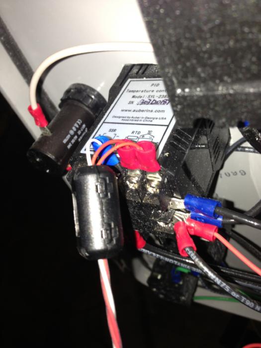
The part external to the control panel is shielded but the inside section is not. Should/Can I make a change here that would help? I will pick up the sleeve tomorrow and try it out. I am a little confuse of where to put the sleeve/sleeves. Close to the panel? Exterior or Interior. I guess I am thinking it should be clamped as close to the PID as possible. Is this correct?
 
From the picture of the probe, the wires are not shielded and are acting like an antenna for the spark module noise. A quick and cheap test is aluminum foil wrapped around the temperature sensor leads with a bare copper wire for grounding running a few inches into and in contact with the foil, then attached to the frame to direct noise away from the controller input. A better solution would be a shielded 20 Ga 3 conductor cable to replace the unshielded wires shown that is meant to minimize the noise pickup.
As to the ferrite sleeves, as close to the controller as possible is the normal installation location.
 
The ferrite sleeves worked. I also had to hook the ground up in this manner.
Igniter to ignition module and also gas controller to frame.
Thanks for all your help

image-3613138847.jpg
 
Hi everyone, been on this forum for a while and just now realizing that this is my first post.

Anyways I just got in a bunch of my parts to get this thing set up and I did a dry run with out hooking anything up to the gas, just all the electrical stuff to see if I could get it to work. To my surprise when the PID called for heat I got spark and everything on the first try and then it eventually timed itself out. Here are my questions: Is there a thermocouple that is suppose to be hooked up separately to the pilot light? How does the system know that the pilot is lit? Secondly I have no idea how to connect the 1/4" copper pilot tube. All I have is what appears to be a brass fitting that screws into the gas valve that has a 1/4" hole through it. While the tube fits pretty snug in there I don't see how its suppose to compress to form a seal.

Any help would be great. I'll post pics of the system once its finished.
 
The rod that the igniter is sparking off of is also a flame sensor. Let me know if you would like a few pics as I have the same set up.
 
Saj,
Insert the copper tube into the fitting until it bottoms out, then screw the fitting in about 1-1/2 turns, which compresses the internal ferrule around the tube to make a seal. This is a one time use item, if tube was not at the bottom of the ferrule you will need another compression fitting as once compressed it is not going to open up for the tubing after that.
As to the flame sense, the flame acts like a rectifier converting the AC spark into DC current flow which the ignition module detects with spark ignition.
The thermocouple type control valves use the thermocouple to generate power to energize an electromagnet inside the control valve, no pilot flame, no power to hold valve open and let gas flow through.
 
Thanks for the response. I'm going to try it out with the gas on this Tuesday, hopefully my luck continues and everything works. Also need to find a control panel box to fit all this stuff into.
 
hooked it up to the gas and still had the problem of the pilot shutting off after it was lit, then realized that i never grounded the pilot back to the unit....did that and everything worked fine. I do need to replace the compression valve on the burner side for the pilot, for some reason it didn't get a good seal and leaks gas. Occasionally the gas coming from the compression fitting will lite up and start melting my ground wire. need to wait for the rest of my parts to come in and I can start doing a final install.
Thanks for all the help!
 
The NG orifice is doing it's job correctly, if too much gas all of the flames will be white-yellow or blue with yellow tips, all flames would be the same, not random flames with color.
The occasional orange flame is likely the oil based paint used on the burner burning off or other contaminants blowing though the inside of the burner, not over fuel. Not to worry the paint oils or contaminants will soon burn off / run out and you will get all blue flames.
To adjust the flame level you can adjust the internal regulator in the honeywell valve to limit maximum flame, unscrew the cover and back off the spring to lower the flame, then put the cover back on.

First off thanks for all the help in this thread. Great info that helped me get going really quick.

I currently have a single tier non automated setup and just completed testing of one of my HW values and ignition modules. I am running LP. This all worked great once I realized I have one Auber with a bad relay.

As a separate test to check flame size I ran one burner through the HW valve, ignition modlue and one straight through the LP gas line. As expected (I am sure I read something to this somewhere on HBT) the burner running through the HW valve was not as high as the one running straight from the LP tank.

Would tighting the regulator spring as you described above increase my flame size on LP? The difference was about an inch and a half. (clearly visible after sun down) I love the idea of the automation but hate to think I may spend more time getting up to temps.

Thanks again.

FYI - Yes I did change all the orfices and spings for use with LP. I am running Hurricanes with the LP valve.
 
Would tighting the regulator spring as you described above increase my flame size on LP? The difference was about an inch and a half. (clearly visible after sun down) I love the idea of the automation but hate to think I may spend more time getting up to temps.

Yes, tightening (turning clockwise) the internal regulator spring on the valve will increase downstream pressure to the burner. Keep in mind that the valve has a min and max value that the regulator can regulate... I believe its from 8-12" wc for LP. What is your pressure going to your non-valved burner?
 
Yes, tightening (turning clockwise) the internal regulator spring on the valve will increase downstream pressure to the burner. Keep in mind that the valve has a min and max value that the regulator can regulate... I believe its from 8-12" wc for LP. What is your pressure going to your non-valved burner?

Thanks for the response.

Both were running from a 2 stage low pressure regulator. One burner with a HW valve from a 1/2 pipe, the other straight from the same 1/2 inch pipe.
 
So I hate to dig up an old thread (Not really if it gets results ;) ), but I'm curious if this PID would work as a more affordable option.

http://www.ebay.com/itm/New-Digital...953?pt=LH_DefaultDomain_0&hash=item257b0a8901

I assume it'd be wired like in this photo?

It should work to drive an SSR, but it doesn't have very good documentation on it. It seems like it's relay output for both of its outputs and it didn't say the magical word "SSd", which is short for solid state drive, so there is a slight chance it won't work out of the box as intended. It also doesn't look like it has very good tuning abilities because it has 3 built in settings. Again the verbiage is very vague and I don't know if that is referring to its ability to heat, cool, and heat/cool simultaneously. In any case, at less that $30 it could be worth buying one and testing it out. If it doesn't work, just go buy an Auber for $45 and use this one to control a kegerator. No real loss there.
 
Ha, actually, I think you just talked me into the auber...

Sent from my SCH-I605 using Home Brew mobile app
 
I have a MYPIN TA4. It works. The documentation sucks but there are enough threads that explain how it works. With that said, if I had the extra money to spend I would switch to Auber, they are just easier to work with.
 
Did you use the version with relay output or ssr? Was it wired to the s8610u like in this example? Did you need an ssr? Sorry for the barrage of questions, I need to cut somewhere and half way through my build this is probably the place...

Sent from my SCH-I605 using Home Brew mobile app
 
Ok... I thought I read that if I bought a pid with relay output, an ssr isn't necessary for this setup... Did I misunderstand? Is there an ssr in the original schematic I'm missing? If not, why does this pid require an ssr and the auber doesn't? Sorry for my ignorance, I appreciate the help of the community!

Sent from my SCH-I605 using Home Brew mobile app
 
For tat schematic you posted today you don't need an neither SSR nor PID with SSR only output. That PID you mentioned (TA4 RNR) has a relay output and fits perfectly for that setup.
 
Thanks! That's good news, it'll save me $50 on pids alone.

Sent from my SCH-I605 using Home Brew mobile app
 
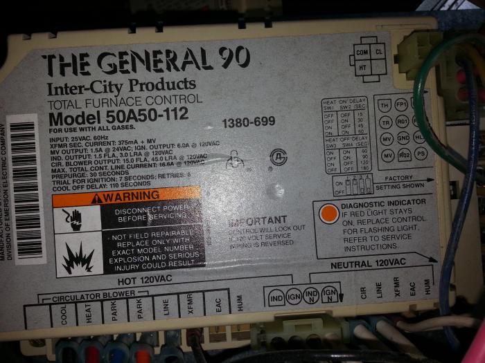
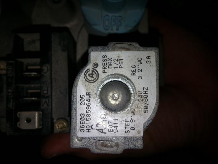
Okay, so I just got a ton of things in the mail to build my control panel. As luck would have it, I was given a gas valve(36E03 205) and control module(50A50-112) from a salvaged furnace (Both supposedly work). Can I work these into my Herms setup by modifying my previously posted diagram?

Gas_Control.jpg


20140329_175955.jpg


20140329_180033.jpg
 
That module and valve combo is for a 30 second pre-purging hot surface ignition setup. Your diagram is an intermittent pilot setup.
 
I have installed my gas system/burners and first and foremost, I would like to thank Sawdustguy for starting the thread and for all the useful information. There were several others contributions that helped as well, thank you. My gas system works as advertised. I flip a switch and the burners light right off.

My set-up: Brewtroller 4.1, Y8610U regulators, the suggested pilot light, 3/8" gas lines, banjo burners, (BG-14) with 3/32 orifice, burners mounted 2" below surface of the stand, no burner shields but also no wind in my garage, and running natural gas.

My problem: Tested the burners with 4 gallons of water. The water would reach 200 degrees but go no higher and it took 48 minutes to reach 200 degrees.

I would really like some further info on what i could do to get my water to boil.

Burners closer to the pot? Larger gas lines?

Thanks in advance. :mug:
 
The burner being 2" below is really close. You could be oxygen starved. Mine is set at 3.75" and still touches the keggles. You may want to try them a little lower to see if that helps.
 
Sounds like 2 problems, orifice is too small, which can be verified by closing the air shutter until flame tips turn yellow. If more than 50% closed you need to enlarge the jet opening, typically 1/8" for start on NG, and increase by numbered drill size until shutter is 80% open. Second problem is burner is still to far from the pot/keg bottom, as long as the light blue inner flame is 1/2" below the pot/keg bottom combustion will complete normally with no sooting. The clearer outer dark blue flames should be in contact with the heating surface for maximum effect like the kitchen range burners do.
Another problem is lack of flame venting from flat bottom pots on typical Brutus stands, a 1/2" spacer will make a significant difference in the way the burner will perform as 1/2 the combustion air flows over the burner, 1/2 into the burner.
 
I hope this is the right thread to post this question in. 2 questions. I am almost complete with my automated system. I am using the honeywell valve with the pilot. Electrically everything works great. I can control the valve with the temp sensors and my bcs462. My big problem is the connection from the orifice (LP style with the 1/4 turn valve) to the black iron pipe that runs from the honeywell valve to the orifice piece. I have an adapter in there now (1/2 to 3/4") but no matter what I do it leaks there a little. The orifice has a bevel on the end so I think it is for some type of compression, the black iron is straight 3/4 npt. Can someone give me an idea of the proper adapter to use there? I do not have the same problem from the hose coming off the tank into the black iron, just at the orifice. This is the orifice I have http://www.brewershardware.com/Valve-and-LPG-Orifice-for-BURN10.html
My second question has to do with air flow. With the valves all the way open I get yellow at the tops of my flame. I am not sure if that is too much air or too little although if I close the vent off they go all yellow and wavey. The burner was High pressure before I changed out the orifice. I am wondering if I should drill out all the holes or make the orifice larger.

thanks and this thread has a ton of great info.
 
Trying to connect to the flare fitting with pipe fittings is not going to work as the threads and method of sealing are not compatible. You would need a 3/8" female flare X MIPS fitting with pipe fitting adapter at a minimum, better is a 3/8" OD gas flex with 1/2" MIPS ends. Most people use the 12"-24" 3/8" gas flex which is already built with flare ends and MIPS adapters and is available from the big box building supply stores. Just remove the adapter from one end and attach the flared gas flex to the orifice fitting, the other end adapter will thread into the gas valve.
The yellow flame tips are probably due to the gas leaking at the orifice connection as the orifice is usually just right for the banjo burners.
 
Got got the 3/8" yellow pipe this morning. That will wort perfectly plus allow me to move the valve to a more convenient location. Thank you. I'll post some pics when its all done.
 
Back
Top