Ok, I'm just about done with my new CP and I realized I just exhausted my electronics knowledge. Sorry for the length here but I have to 'splain before I can ask a question.
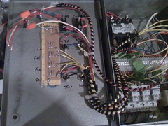
For a couple of reasons, my CP is fed from two separate circuits: A 30A 240V circuit for my HLT element, and a 20A 120V circuit for my RIMS element and all the other electronics. Both circuits are GFCI protected and are completely isolated in the CP. Each element is cycled by a PID controlled SSR, but I also have a switch for each that energizes a contactor which supplies power to the SSR. The SSR is always switched by the PID, but unless the switch is turned on for that element, the element gets no power.
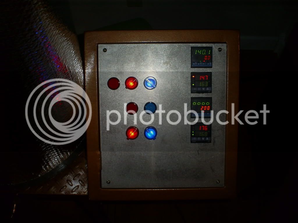
I also have separate indicators (LED) that I want to turn on when the element is actually heating, which means they are connected to the output of the SSR along with the element. That way, I can tell by a glance if the element is on. Ok, so here's the question: For the 120V element, it's a straightforward connection. I'm using 120V LED indicators from AutomationDirect. What I haven't been able to figure out yet is how to get the indicator to work with the 240V element. If I was feeding 4-wire 50A to the panel I could just use the neutral, but in this case the circuits are separate and I'm concerned that the 5mA that the LED draws will be enough to trip one or both of the GFCI's if I "borrowed" the neutral from the 120V feed just for the LED, not to mention the fact that I want to do it the right way and not cut any corners. I'd rather not have to use a stepdown transformer just to power a stupid indicator. I'd be game to use a CR circuit to reduce the voltage, but while I know what a CR stepdown does, it's been way too many years since my basic electronics classes to remember how to calculate one.
Any electronics geeks out there who can help?
Thanks!
MrH
For a couple of reasons, my CP is fed from two separate circuits: A 30A 240V circuit for my HLT element, and a 20A 120V circuit for my RIMS element and all the other electronics. Both circuits are GFCI protected and are completely isolated in the CP. Each element is cycled by a PID controlled SSR, but I also have a switch for each that energizes a contactor which supplies power to the SSR. The SSR is always switched by the PID, but unless the switch is turned on for that element, the element gets no power.
I also have separate indicators (LED) that I want to turn on when the element is actually heating, which means they are connected to the output of the SSR along with the element. That way, I can tell by a glance if the element is on. Ok, so here's the question: For the 120V element, it's a straightforward connection. I'm using 120V LED indicators from AutomationDirect. What I haven't been able to figure out yet is how to get the indicator to work with the 240V element. If I was feeding 4-wire 50A to the panel I could just use the neutral, but in this case the circuits are separate and I'm concerned that the 5mA that the LED draws will be enough to trip one or both of the GFCI's if I "borrowed" the neutral from the 120V feed just for the LED, not to mention the fact that I want to do it the right way and not cut any corners. I'd rather not have to use a stepdown transformer just to power a stupid indicator. I'd be game to use a CR circuit to reduce the voltage, but while I know what a CR stepdown does, it's been way too many years since my basic electronics classes to remember how to calculate one.
Any electronics geeks out there who can help?
Thanks!
MrH