• Please visit and share your knowledge at our sister communities:
  • If you have not, please join our official Homebrewing Facebook Group!

    Homebrewing Facebook Group

Electric conversion

Homebrew Talk

Help Support Homebrew Talk:

This site may earn a commission from merchant affiliate links, including eBay, Amazon, and others.
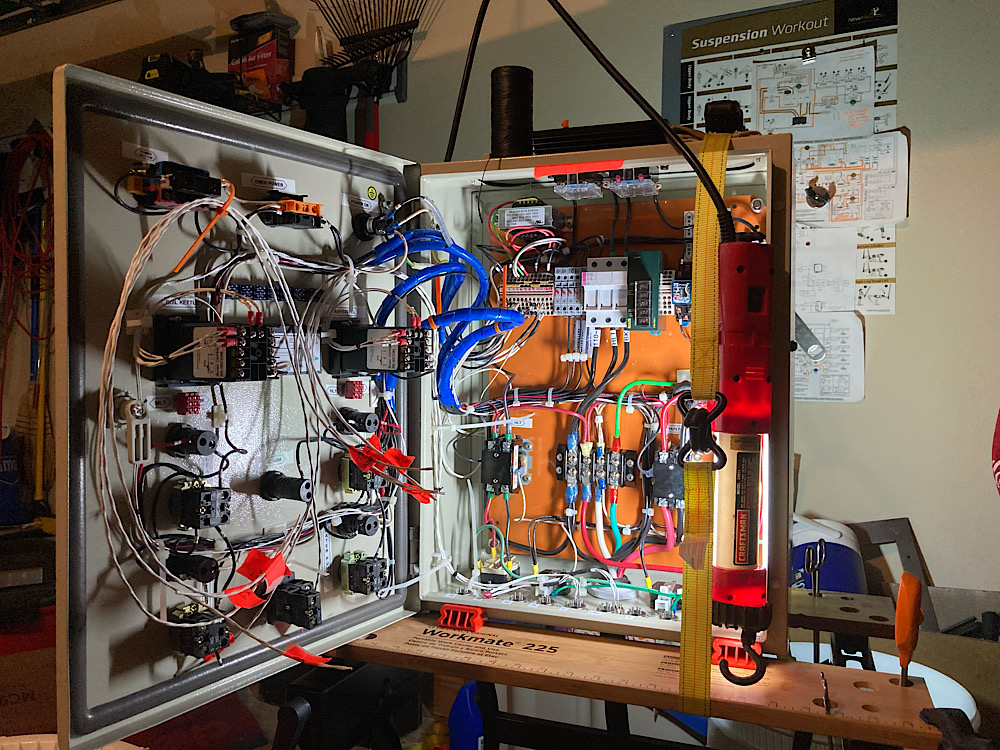
Got holes cut for the XLR receptacles for temp sensors and float switches. And most of the panel components located. The heating element receptacles took a bit to get righgbsince I needed a hole a bit larger than 1-3/8, but the largest punch I had was 1-1/4. A little work with a half round file, and I’m pretty happy. View attachment IMG_4702.jpg
View attachment IMG_4703.jpg
 
So, I’ve had some time off like a lot of people. I’m back to finishing this long overdue project. Highly embarrassed I’ve taken this many... years. Anyway. Here’s it mostly finished.
it has a safe start interlock to cover the pump and heating element switches, the water pump has a second mode switch to toggle between normal recirculation for the HLT, or sparging, and a bunch of bypass switchesto bypass element protection, grant, and sparge float switches in case they fail.
 

Attachments

  • 4AE595A4-DA09-4168-A57D-10CB8448AD54.jpeg
    4AE595A4-DA09-4168-A57D-10CB8448AD54.jpeg
    391.2 KB
  • DEB4A51F-74E7-4275-B4D1-0AD171B16357.jpeg
    DEB4A51F-74E7-4275-B4D1-0AD171B16357.jpeg
    390.2 KB
Just need to bond all the receptacles time case ground, and the inside should be done. Hopefully I’ll get that knocked out tomorrow, and start on the wire harnesses. Still have to fab the HLT. HERMS coil is more or leas shaped. Also borrowing a MAP torch this weekend to try silver soldering up the grant.
68320BCE-315E-4BB6-A4F0-650F0DE8AD5F.jpeg
 
For a lot of my low voltage, temp sensors, float switches, and float switch bypassing switches I used scrap M27500 aircraft wiring. Most of it was shielded twisted pair, but I was lucky to have a little triple twist for the temp sensors. I like this stuff because it’s Teflon jacketed and can the high temp pretty good. Bumping into it with a soldering iron won’t immediately melt the insulation off of it like THHN. It was probably overkill, but I added shielding drains to ground to prevent the high current from inducing any EMI. My soldering is a little out of practice, and I am using a crappy Weller soldering iron rather than a soldering station (miss having one of them). For what it’s worth here ya go.
01D9CB33-CAF7-45CE-B244-497736FEAF00.jpeg
34C72C2E-A764-497D-9F3C-982F4058049B.jpeg
5A74C38F-8090-42DE-8F68-8EB5846A9C85.jpeg
C8294FC5-0FEB-4B1B-827B-A631BE79C32D.jpeg
 
I will also say having bout 6 Meters of PT100 metal stainless braided cable that stripping the fiberglass inner insulation off the conductors is a bit of a pain. I’m starting to figure out some tricks.
7F4D7566-6E4A-4B3D-8EB3-910627BBC0FD.jpeg
 
Started smoke checking the system. The safe start interlock relay had issues due to the silkscreen ID on top of the relay, stamped ID in the Boynton if the relay, and the relay socket all having at least one error each not matching the data sheet... thanks a lot Uxcell.

The power meter ended up getting installed upside down because they installed the data sticker upside down, and I used that for reference.
The water pump works fine, but doesn’t turn off when I turn off the main pump switch unless I trip the float bypass switch, so I have to investigate that a little.

An anomaly I have is that my heater indicator lights are always on dim even when the switches are off. Power goes through a fuse, to the SSR, through the heater element contactor, then to the element jack. Is it normal for an SSR to allow some power through when off? I have to figure that out too. At least I know there’s no power downstream if the contactor.
 
...

An anomaly I have is that my heater indicator lights are always on dim even when the switches are off. Power goes through a fuse, to the SSR, through the heater element contactor, then to the element jack. Is it normal for an SSR to allow some power through when off? I have to figure that out too. At least I know there’s no power downstream if the contactor.
This is normal. An SSR isn't a mechanical switch that interrupts voltage and current. It behaves more like a resistor that can be switched from a high value to very low value. The "off" state is a high value of resistance, so that only a few mA of current can flow, but that is enough to dimly light the LED indicator if the element is not connected. If the element is connected, then the few mA of current flows thru the element, and the voltage drop across the LED (and element) is not enough to light up the LED.

Brew on :mug:
Nothing was plugged into those plugs. In retrospect I should have tapped the power on the downstream side of the contactor... thanks.
 
Back
Top