• Please visit and share your knowledge at our sister communities:
  • If you have not, please join our official Homebrewing Facebook Group!

    Homebrewing Facebook Group

Electric burners - Any builders out there?

Homebrew Talk

Help Support Homebrew Talk:

This site may earn a commission from merchant affiliate links, including eBay, Amazon, and others.
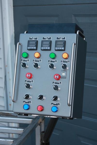
Wow, looks awesome! The panel looks similar to Kals which I am aiming for. Excellent job thus far. Can't wait to see the whole setup in action.

What are you using for a HLT and Mash Tun?
 
Will get some more shots in a few weeks-month when we wrap up our stand and get the armature all set up. I think it will be a little easier to get a good shot of it once it is in its final position.

Thanks for all the help guys. No way I could have come this far alone.

Looks great Cidah I should have you come wire mine..I can pay you 4.5 lbs of barley!
 
Excellent. Great wiring!

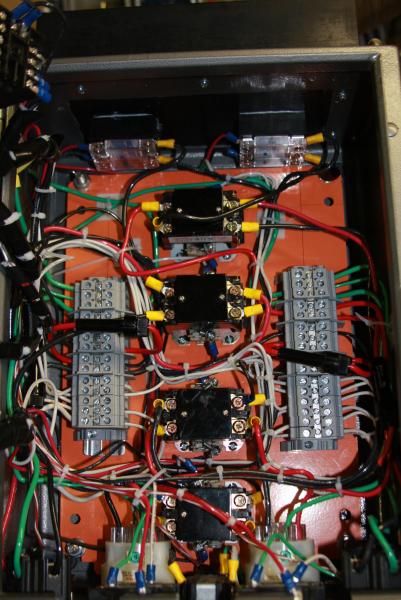
Thanks!! There is a lot of wire in that beast! I everything has a dedicated line in and out. The only exception being that I daisy chained the hot and neutrals on the right side PIDs. I will also daisy chain the alarms on both of those, and might put in an on - off - on switch so I can set the alarm for either the HLT or probe for exiting wort from the eherms. But I am still recovering a bit until the eherms portion will fully take off (buying the coil and other fittings).

Wow, looks awesome! The panel looks similar to Kals which I am aiming for. Excellent job thus far. Can't wait to see the whole setup in action.

What are you using for a HLT and Mash Tun?
Yeah the key difference between this one and Kals would be enclosure size (superficial) and guts. I think Kal offers a build with twice the amperage/service for a single element but doesn't have a build with two sides functioning at once yet (I think). Definitely couldn't have made it this far without Kal's help and ingenuity though. Mine is a hybrid between Kals design and the guts from my first build.

Most important is that it can run 60 amps, 30 amps per side, simultaneously. This was part of my design from the start because I found my buddy and I doing double and triple 11g batch brew days to play a little catch up if we weren't brewing for a while. Having another element really helps out for heating strike and sparge water in between while the first brew is boiling.

I have a 15G HLT (megapot) and a 25G BK (megapot) and then the blichman MT in 20G size

Looks great Cidah I should have you come wire mine..I can pay you 4.5 lbs of barley!

haha too funny. I actually really enjoyed this project. I love wiring the stuff up.

I couldn't help but put in parts that are my own spin on Kal's build, but as I told him. Simply never would have been at this level without his ingenuity.
 
just noticed you can't see the double sided nature of my build in the other pictures so i will attach this one. Each side is fully redundant with the right side having all the hardware for a full eherms. That is the next direction I am moving to. Mechanical stirrer, etc. (that is what the lower red switch on my panel will likely be for.)

IMG_5402.jpg
 
Nicely done. You should be proud of what you've built here. It will give a lot of information to those that want to follow in your footsteps.
 
Nicely done. You should be proud of what you've built here. It will give a lot of information to those that want to follow in your footsteps.

Thanks yjfun - appreciate it!!

Without the help of people like you on this forum I never would have learned what I have, or been able to conceptualize and design something like this in the relatively short time it took me to build it (about 3 weeks of passive building to get it done). The hard work is definitely done on the front end before you even touch your tools.

It not only helps me step up my brewing game, but really taught me a lot about electricity in general.
 
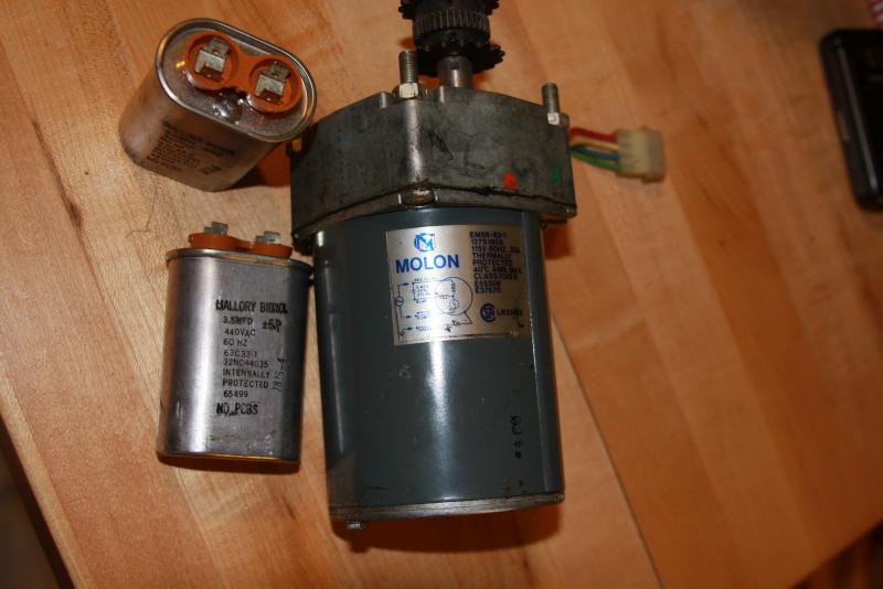
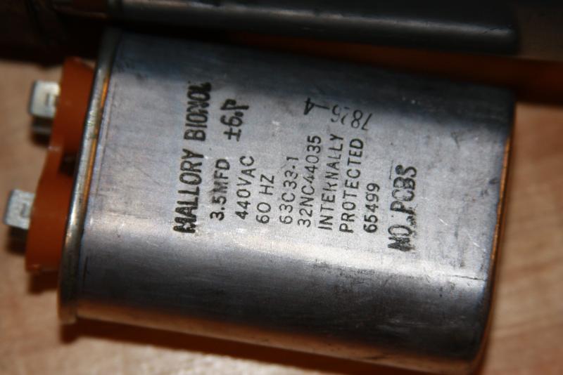
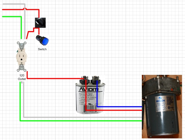
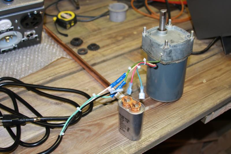
I am wiring a motor to use as a stir paddle for my HLT. It came with two 440V capacitors and I am trying to decide if they are needed and if so how to wire them in.

I have two questions:
1. Should I use the capacitors? (I assume I should use only one even thought they supplied 2, as per the wiring diagram)
2. If yes, how do I wire them in?

Here is the motor

I am unsure if the capacitor is needed for my application. I was talking to a couple electricians and they thought it might not be required and said I would be ok leaving the capacitors out.

That said I see at least one capacitor represented in the wiring diagram (not sure why they gave me two).

I have tested the motor wiring a hot to the red, neutral to the white and ground to green. It runs. But I am not sure if I am under feeding and potentially damaging the motor.


Thanks a ton for your help guys, I really appreciate it.

1.jpg


2.jpg


3.jpg
 
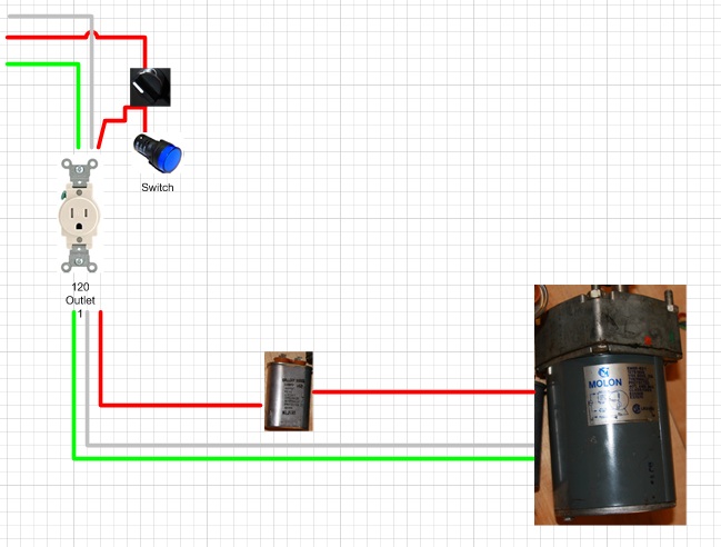
I read that diagram as requiring a capacitor after the plug (and after a switch if you were planning on putting one inline down from the plug).

So this is what I was thinking. If I wanted to make the motor turn clockwise I would simple use the blue wire.

Motor.jpg
 
That's a motor run/start cap. The cap is there to help give the motor the initial charge it needs to start turning. Also, it looks like it stays in circuit during the run (some motors have a switch that will shut off that portion of the circuit once the motor is turning).

You need the blue wire either way, if you want to run clockwise you'd apply power to the blue wire and attach to one head of the cap. Then attach the red wire to the other cap connector.

And yes, this should be way after any switches that you have for the motor. The cap for my HLT stir is placed immediately next to the stir motor itself and I just have the 3 wire extension cord running to the stir motor/cap assembly as it sits on my HLT.
 
I read that diagram as requiring a capacitor after the plug (and after a switch if you were planning on putting one inline down from the plug).

So this is what I was thinking. If I wanted to make the motor turn clockwise I would simple use the blue wire.

Do you have a requirement that you can run the motor both clockwise and counter-clockwise? If so, you can wire up a DPDT switch to do this. (I did this for motorizing my barley crusher so that I can reverse the motor if I feed my tie into the crusher. :tank: )
 
Thanks for the information yjfun and bruin.

Based on your comments and advice I updated the wiring diagram (in my visio cartoon styled attached diagram) and grabbed some of the properly rated capacitors on amazon for an optimal motor performance/life.

With that I can use this over powered beast to stir some water haha.

Do you have a requirement that you can run the motor both clockwise and counter-clockwise? If so, you can wire up a DPDT switch to do this. (I did this for motorizing my barley crusher so that I can reverse the motor if I feed my tie into the crusher. :tank: )

No reason to need to run it both ways, in truth I don't really need it to go both directions. Just was saying a "what if". I bought two of these motors so who knows what cool use I might find for the second motor down the road....

Motor.jpg
 
Last edited by a moderator:
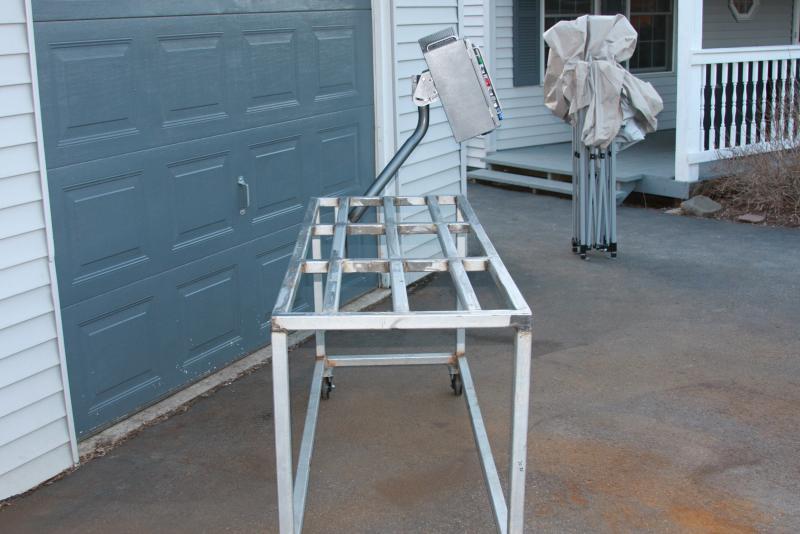
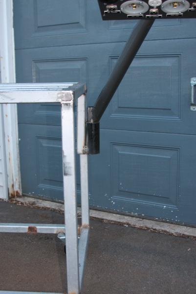
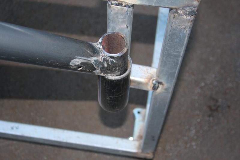
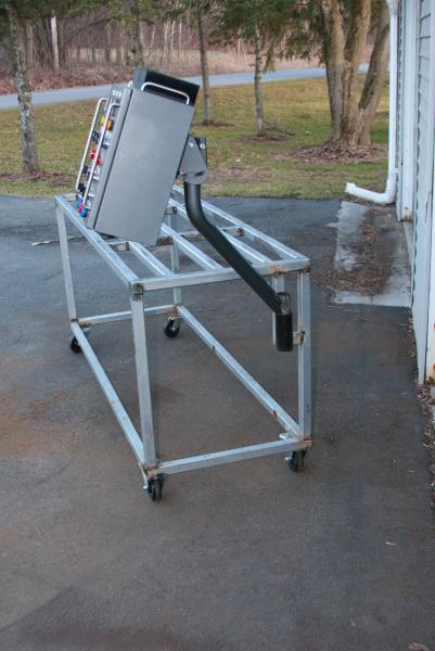
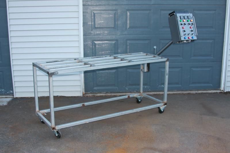
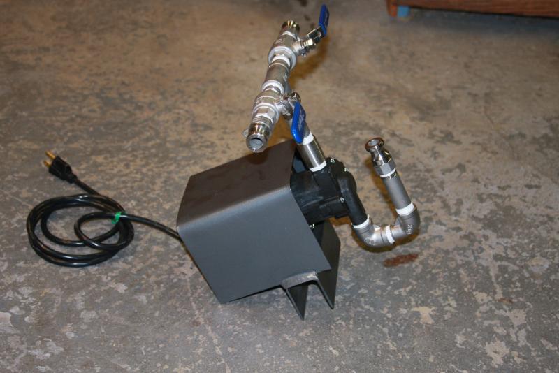
Some new items for the build. Shrouds for the two pump motors have been fabricated/painted along with the armature!

And my crazy @ss buddy just bought a 3 roller monster mill :D

1ab.jpg


2ab.jpg


3ab.jpg


4ab.jpg
 
I think 50' is too much could only find 20' locally and saw this on Tiber Brew's build thread too. Hope this helps.

nice!

as for the length of your copper tubing, I would suggest 25ft. I had planned on putting together two 25ft tubings (as you can see in the first pic) but it came to pretty much the height of the keg itself. 25ft fits perfectly. leaves room for the element and is about 2-3 inches from the brim....
 
Yeah I went with 20 ft of 3/8" (OD) copper for my herms. Seemed to work well when tested, although the flow wasn't super high - but seemed sufficient. But I am already using 3/8" hosing to run from my pump manifold to my HLT and to my MT, so figured it would be restricted anyways. If you go longer than 25 ft with 3/8" I can see where flow will really suffer due to length.
 
Yeah I went with 20 ft of 3/8" (OD) copper for my herms. Seemed to work well when tested, although the flow wasn't super high - but seemed sufficient. But I am already using 3/8" hosing to run from my pump manifold to my HLT and to my MT, so figured it would be restricted anyways. If you go longer than 25 ft with 3/8" I can see where flow will really suffer due to length.

All my hose is 1/2'' so I plan on using that size in copper. I have read quite a few folks using 50 feet, especially all the guys who copy Kal's build which uses 50 ft stainless. I bet if you bumped up your hoses to 1/2'' it would be all right, but truthfully have no idea. I do know that you want to have as little restriction as possible on the front end before the pump, and that you can restrict after the pump more liberally.
 
All my hose is 1/2'' so I plan on using that size in copper. I have read quite a few folks using 50 feet, especially all the guys who copy Kal's build which uses 50 ft stainless. I bet if you bumped up your hoses to 1/2'' it would be all right, but truthfully have no idea. I do know that you want to have as little restriction as possible on the front end before the pump, and that you can restrict after the pump more liberally.

Yeah all of my plumbing is 1/2" except from my value manifold to the HERMs input. I bought 3/8" for this. I'm not too concerned about the flow. I'd rather run it slower and avoid the risk of getting a stuck grain bed during mashing recirculation.
 
Cidah, I've finally gone through this entire thread and have a reasonable idea of what you've done, gone through, and why you did what you did (e.g. two 30 Amp circuits to one control box). Do you have some scematics that you can send me (to my email) and also any parts list and sources would be appreciated. I would like to build on some of your ideas, although I don't think I will go with two 30 AMP circuits.
Thanks!

You have read a roller coaster of my learning curve with electric :D On post 1 there are some link you can jump to relevant sections of my thread (FYI)

No problem! I have my drawings in visio, but I don't have them on hand this second. Did you want the drawings for one side or for the entire enclosure (both sides). Would you mind pming your email to me?

FYI - I ran through the wiring schematics and the final product with my brother in law (licensed union electrician). So while I am not an electrician the concepts on paper and in the box were reviewed by at least one (had help from a couple others on as well).

It is certainly a little more $$ to go with the two 30 amp gfi feeds. However that is mostly a factor of the 30 amp GFIs that you have to buy. Aside from that if you get your enclosure on ebay with that free shipping on other items deal... you really aren't spending a ton more money on hardware to get two simultaneously running elements (IMO obviously well worth it).

If you need help figuring out why I did what I did, feel free to ask and we can even chat via phone if that works better for you.

Cidah,

PM sent. Yes, I am hoping to bundle a bunch of stuff into the enclosure, and was likely going to go with the bigger enclosure to have room. My issue (mentioned in my PM) is that I already have a single 30 Amp 240VAC circuit into the intended room (my laundry room). All of this is tentative, I might just bite the bullet and have another circuit run, in which case I might go bigger. I also like the idea of redundant components, but am also toying with the idea of allowing (in addition to or in place of) a 120VAC source and having an additional 120VAC element in the HLT (or running the 5500 Watt 240VAC element at 1350 (1/4) from the 120VAC source).

I'm still at the beginning of this, but wanted to start to layout parts and prices (using your build as a model).


Hey, has anybody ever wired one of these suckers in so you can see how much power your brewery is consuming? :) http://www.renewcanada.com/digital_readout_ac_kwh_meter_240vac.html
 
Never put one on a brew system but I have put them in a couple of peoples houses when they converted them to duplexes. You can purchase them from just about any electrical supply house.
 
Never put one on a brew system but I have put them in a couple of peoples houses when they converted them to duplexes. You can purchase them from just about any electrical supply house.

I was somewhat kidding (size wise), but I do like the idea of some sort of metering display.
 
I figured you weren't serious but it would look kinda cool stuck on the side of your controller.:)
 
I am planning on insulating my kettles as well as the MT for my eherms. wanted to check in with anybody that has done this so far.

I am looking at using these

Ultra-Flexible Foam Rubber Insulation

Temperature Range: Plain back: -295° to 220° F; Adhesive Back: 20° to 180° F
Heat Flow Rate (K-Factor) @ 75° F: 0.25
Density Range: 3-6 lbs./cu. ft.
Color: Black

Soft Buna-N/PVC foam creates an extremely flexible insulation sheet. The material is elastomeric and has a closed-cell construction for moisture resistance. Can be used outdoors if coated with latex paint (sold separately). Meets ASTM E84 25/50 for flame and smoke. Install plain-back insulation with contact adhesive (sold separately).

White latex paint is compliant under all state VOC rules in effect on November 1, 2011. Contact adhesive is compliant under all state VOC rules in effect on November 1, 2011.


But am not sure if I should go with 1/2 in or bump it up to 3/4, etc. ultimately I do want well insulated kettles all around so I can maximize the volumes that I am boiling in, etc. Any experience from you guys?

Plan was to get this and then use a contact adhesive to stick the foam to reflectix. This way I can remove the foam and get some shiny from the reflectix without damaging it. Wan planning on using velcro to attach and remove the insulation blanket.
 
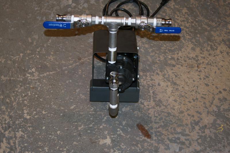
Some pictures of the rig and the armature! + pump shroud with pump installed.

1.jpg


2.jpg


3.jpg


4.jpg


5.jpg
 
Looks good, but I do have a question.

What are your thoughts on how you will drain the pump when you're finished?

Ed
 
Looks good, but I do have a question.

What are your thoughts on how you will drain the pump when you're finished?

Ed

Good point, I didn't really notice the inlet curves.
While it may be slightly more convenient to hook up that way, a bunch of 90 degrees before the inlet isn't a great idea anyway - it can provide some input restriction that makes it harder to keep the pump primed.
 

Latest posts

Back
Top