• Please visit and share your knowledge at our sister communities:
  • If you have not, please join our official Homebrewing Facebook Group!

    Homebrewing Facebook Group

Electric burners - Any builders out there?

Homebrew Talk

Help Support Homebrew Talk:

This site may earn a commission from merchant affiliate links, including eBay, Amazon, and others.
I measured all the stuff out, then checked clearances with measure, then with actual parts in place and looks like I will have plenty of space. The space will require me to keep things neatly wired, but that is part of the beauty of the electrical rigs. Nice neat and secured wiring! :D If I went with the larger box I think it would have been too much space. I like the current layout I have because it isn't over crowded, but uses up the space on the panel.

Can't wait to settle up the painting and then to get the hardware in place for wiring. Still waiting on my switches from china though.... suckers. now they are past due and it would really suck to have them refund me with no switches in hand. Hopefully they come in this week right after I get the painting done.

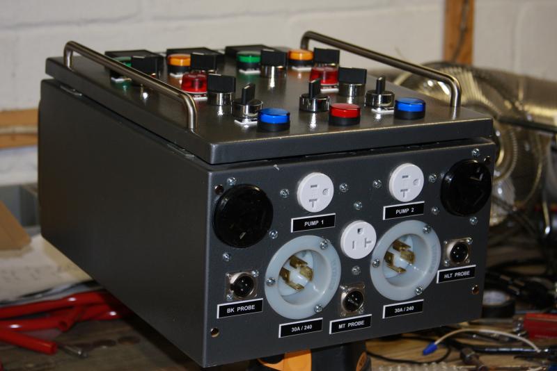
the cool part about the receptacles is that with the current set up I will have the ability to have 3 120 outlets. 2 are spoken for with pumps with one unclaimed. This will either be for a third pump down the road, a ventilation hood fan or a mechanical stirrer for the HLT when I complete my eherms.

I will have to come down for a brew day when your all up and running!!! Will be interesting to see and I can always bring down 4.5 lbs of grain to add to the batch!! LOL
 
I will have to come down for a brew day when your all up and running!!! Will be interesting to see and I can always bring down 4.5 lbs of grain to add to the batch!! LOL

ha - you said it! :cross: I simply can't wait to get this off and running. I am taking deep breathes to keep my patience on the project so:
(a) I don't drive my wife crazy hanging out in in the wood shop (cellar)
(b) I don't rush a step and compromise all the hard work so far :D
 
Polished up my wire diagram last night and now I am feeling pretty good.

1. Panel painted.
2. Some receptacles installed.
3. Wiring diagram finalized

All that is left is for me to paint / attach the swing arm hardware to the back of the control box. Once I do that I will be able to wire this bad boy up!

.... of course I am still waiting on my last PID as well as a bunch of switches from china... Hope I get them before the week closes up.

Will post some pics of the progress when i can!
 
OK so some new picks!

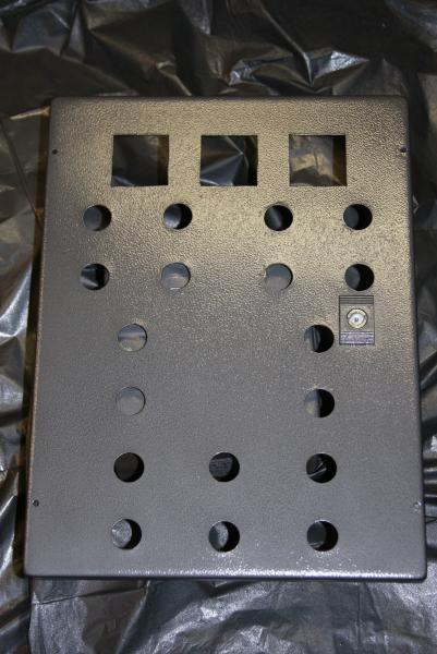
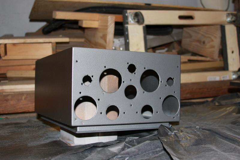
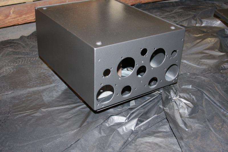
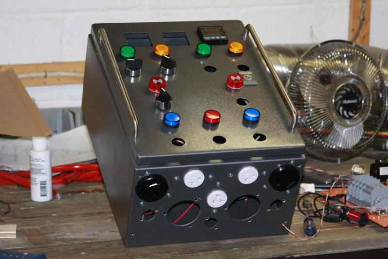
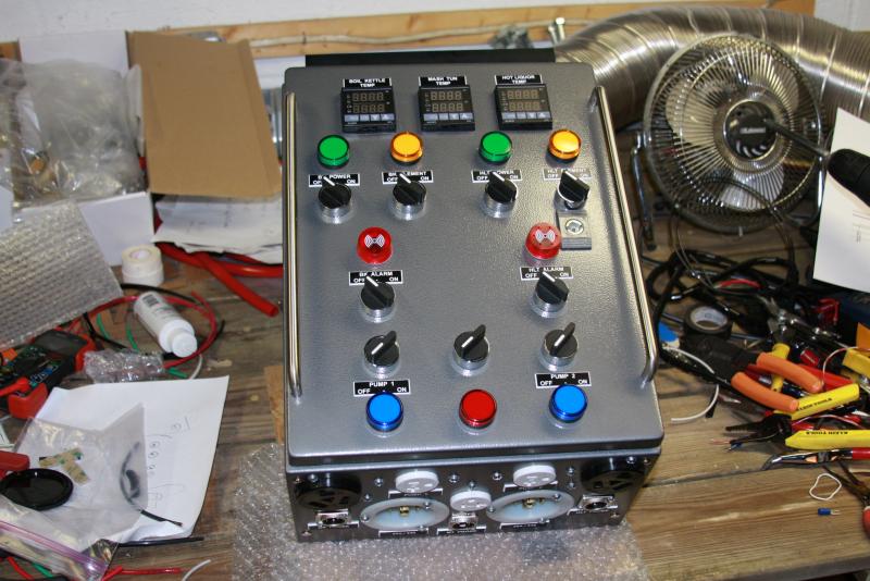
First we have some paint shots and then some partially filled in slots for the panel. Now it is really taking off. If I have my way I will be able to wrap up the wiring this weekend!!

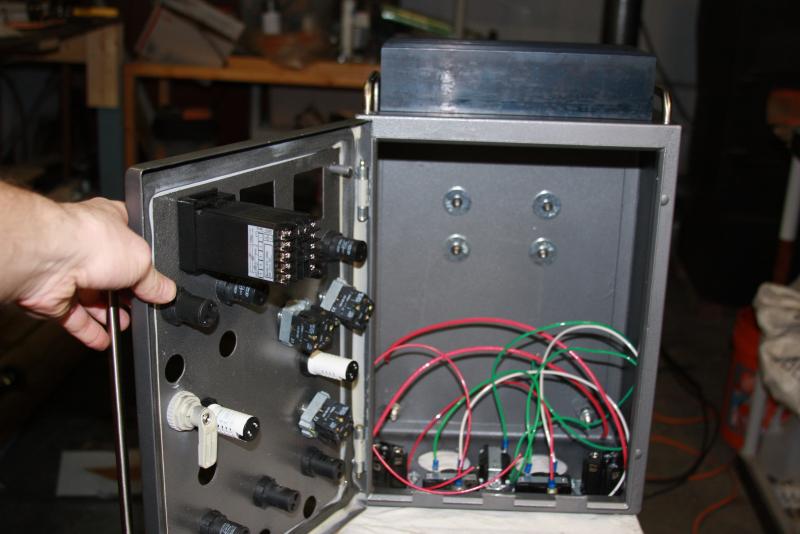
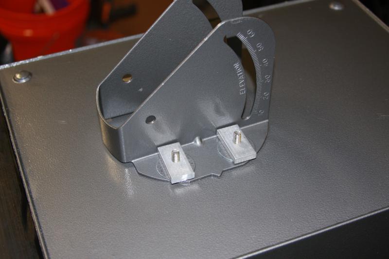
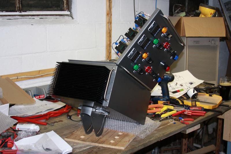
Other pictures include my swing arm. I pulled down a satelite dish arm from outside my house and cleaned it up and painted the mount. You can see the angle of display will be adjustable. Since I needed to mount that before wiring (once back plate is in hard to access) I added that now.

Before I start wiring I need to solder my probes and put in the last of the receptacles.

X.jpg


X1.jpg


Y.jpg


Z1.jpg


Z2A.jpg
 
The control arm mount in place and a sneak peak at the panel with some of the lights and switches filled in.

Z2B.jpg


Z2C.jpg
 
Seeing how close you are to finishing helps motivate me!

What did you paint the panel with? Came out great!!

I am glad I am motivating you!

First let me say I hate painting, it usually is the part where I screw up hours of hard work. My wife looked at the paint enclosure perplexed, paused and said, "It looks professional". Haha - not sure I would go that far but I really thought it turned out pretty well all things considered.

I went with rustoleum's grey hammered finish (aerosol). If they would have had a burnt orange or red I might have went that route, but I actually like the grey too (didn't have the red in the HD where I picked it up). It says you can apply direct with no primer but I lightly sanded and primed anyhow. The black was too dark for me. I really wanted to go with the silver color, but I compromised for the grey based on opinions from my wife and buddy. We plan to paint the whole steel stand with this color as well as the control arm so it looks uniform.
 
Inline Splice:

I have read that inline splicing/soldering of a wire is not allowed in household wiring according to code (on electrical forums so I am not sure of the code myself). Is there a "best" way to do this? I am going to be adding about 20 feet of 10-4 wire to 8 or so feet of 10-4 dryer cord. I would like to use the best low profile way so it looks good and is functional. After reading it wasn't to code I thought maybe there was a better way to do it.

I know this wouldn't be house wiring anyhow, it would be extension cord wiring. But this will have a lot of amperage to it so I wanted to go with the best way possible. Any of you wire benders out there have suggestions?
 
You can't use regular wire nuts and do an open splice in a wall or ceiling but it is perfectly fine to run both ends of wires into a junction box and splice with wire nuts in there. Another option is to buy a splicing kit from an electrical supplier. Tyco makes one that has 4 set screw style butt splices in a preformed plastic housing that you then cover with heat shrink. The cheapest way is to use individual mechanical splices (set screw or crimp style) and heat shrink each one separately and then heat shrink the whole group together.

The idea is to make an unbroken length of wire with no exposed splices that can work loose and start a fire. I have used all of these methods and they all work very well.
 
For this specific application will be an extension cord format (bulk wire at Home depot) with a rubber outdoor rated casing (so I prefer not to use a junction box). I am taking one of these and adding 20 feet of the home depot wire plus the leviton connector to a flange panel mount.

My concern is that the joining is sound even with some movement of the cord. i.e. I don't want the connection breaking or getting damaged if I pick up, move step on the cord, etc (within reason of course).

Was thinking of either butt splice crimps (but they are bulky) or shrink solder connections and then a shrink tub casing over all connections that.


yjfun - you missed the member drive. You could see the pictures of my progress!! :D
 
Last edited by a moderator:
My setup is similar, rather than splicing them I put proper connectors on them so it's like plugging an extension cord into another extension cord.
I bought one of those 4 wire dryer cords and put a leviton twist-loc connector on it. The other cable is a 25ft (10-4) extension that I got at home depot (not the cheapest solution, but I had a gift card so I made it work).
 
I can see the photo's you post I just couldn't edit any of the diagrams. I like your enclosure it's looking good.

If you use one of these you don't have to do any inline splicing:

http://www.lowes.com/pd_246879-1571...entURL=/pl__0__s?Ntt=30+amp&page=5&facetInfo=

They are adjustable from 120-240 volts and 30-50 amps by changing the plug pins.

If you do end up splicing anyway use individual butt connectors and heat shrink and you can just about drive a car over it and not have any problems we do this for commercial spider box cords that see alot of abuse every day. No need to worry about the connections coming loose with a little movement.
 
My setup is similar, rather than splicing them I put proper connectors on them so it's like plugging an extension cord into another extension cord.
I bought one of those 4 wire dryer cords and put a leviton twist-loc connector on it. The other cable is a 25ft (10-4) extension that I got at home depot (not the cheapest solution, but I had a gift card so I made it work).

Yeah I was looking for the cheap way out! :) But realistically I realize this is a lot of amperage and I don't want to save a hundred bucks and lose a life.

I think that I will roll with the shorter factory dryer cords (10ft) that I have for now. However if they aren't long enough it will likely be a full out new 4 prong (like yjfun suggested) and 30ft bulk wire; or leviton connectors as you have suggested. But those leviton connectors are cost prohibitive. I bought some for the panel, but man!

I know I will need to upgrade them... but my wallet needs a little recovery time :D That will give me some tim to sort out the best solution.


yjfun - thanks for the advice! I think I will hook everything up that I have as is (right not that is 10 ft cord with factory 4 prong on it and the leviton connector).


1.[adjustable prong approach] 30ft 10-4 wire ~$2.10 a ft I think = $63
$14 4 prong adjustable plug = $14
(have end connector already so) - total = $77 x 2 = $154

2. [leviton connector]20ft 10-4 wire ~$2.10 a ft = $42
connector ~$40
male twist lock ~$20
(have end connector already so) - total = $102 x 2 = $204

3. [Splice] 20ft wire ~2.10 a ft= $42
butt crimps (have them, maybe $.50)
heat shrink ($5-$10 tops)
(have end connector already so) - total = 52.50 x 2 - $105

For my money I think it would be worth $50 more to have a single run of wire to the plug. Bad part is neither option is cheap. Time to look for deals on 10-4wire! ha
 
Actually this almost isn't a bad deal. I am not sure if that connector will work with the flange receptacle I have though.
 
I am glad I am motivating you!

First let me say I hate painting, it usually is the part where I screw up hours of hard work. My wife looked at the paint enclosure perplexed, paused and said, "It looks professional". Haha - not sure I would go that far but I really thought it turned out pretty well all things considered.

I went with rustoleum's grey hammered finish (aerosol). If they would have had a burnt orange or red I might have went that route, but I actually like the grey too (didn't have the red in the HD where I picked it up). It says you can apply direct with no primer but I lightly sanded and primed anyhow. The black was too dark for me. I really wanted to go with the silver color, but I compromised for the grey based on opinions from my wife and buddy. We plan to paint the whole steel stand with this color as well as the control arm so it looks uniform.

That's the same paint I plan to use, I really like the look of it. What HD did you find the grey at? I ordered the charcoal grey online and they sent me two Silver's before they got it right and sent me grey. So I'm up two cans of silver hammer finish.
 
yjfun (or anyone who can help) - wanted to check something.

should I toss in an inline fuse going from the jumper on the contactor block to the switch? (gold triangle on drawing)

You had mentioned something about possibly putting an inline fuse in where I have marked the gold triangle in the attached picture. Is this a best practice? Right now i had used 10g wire to go from line in to contactor, and contactor to terminal block. However I used 14G wire to run from the contactor jumper to the switch because the jumper wire should not draw beyond its lower amperage needs to activate the LED and close the circuit on the contactor (thereby allowing power to flow to the terminal block.)


if the vote is yes I was thinking I would toss in a 8amp slow blow fuse since the switch is rated for 10amp (just because I have some of them). This way any minor short pulls of power wouldn't blow the fuse, only constant.

Thanks,

Contactor.jpg
 
should I toss in an inline fuse going from the jumper on the contactor block to the switch? (gold triangle on drawing)

After chatting with a few folks and one electrician I think I am safe to leave the fuse out of the mix for this.

I also reason that electricity follows the path of least resistance. The 14g run is about 5x longer that the 10g and has greater resistance as well (only bizarro current would be able to act in a way that could cause issues). All things considered I think the fuse is unnecessary.
 
I think your logic makes sense and wouldn't bother putting one in.

Electricity does like the path of least resistance but between the 14 awg and 10 awg wires it won't care. Those wire sizes are so close and also its such a short run that it will go either way and not care.
 
I think your logic makes sense and wouldn't bother putting one in.

Electricity does like the path of least resistance but between the 14 awg and 10 awg wires it won't care. Those wire sizes are so close and also its such a short run that it will go either way and not care.

I guess if something fries early on, or the wires (the 14g jumper wires) get warm to the touch after a brew session. I will toss an inline fuse just to be safe.

Thanks!

Amost done wiring... waiting on a PID and then it should wrap up nicely! :D

I think I will bench test it with my electricl probes first before I hook it up for a brew day. Make sure my receptacles/outlets are reading the right values, etc. I am looking forward to doing that maybe by the end of this week.
 
Definitely bench test everything before hooking up your elements. Also go over every termination screw and make sure they're tight. I don't know how many times I've had to troubleshoot a system where the installer missed tightening a terminal and things either didn't work or worse fried an expensive component.
 
Definitely bench test everything before hooking up your elements. Also go over every termination screw and make sure they're tight. I don't know how many times I've had to troubleshoot a system where the installer missed tightening a terminal and things either didn't work or worse fried an expensive component.

Sound advice. I have already traced out paths for wiring from the terminal block to components and back as per my wiring diagram for the left side twice since it is complete (will be doing the same for the right side when last my PID comes in this week).

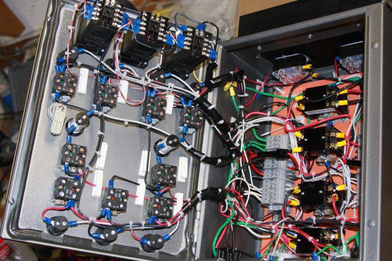
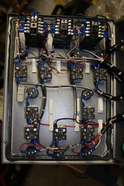
There are a lot of wires in this bad boy because I didn't daisy chain anything. I wanted trouble shooting to be straight forward for each component. Though I am paying the price in spaghetti!
 
Use lots of zip ties and sticky backs. :)

Funny you say that. I am sort of in 3 stages with the wiring. Actual wiring (95% done), checking wiring (50% done) and "reining" the wiring in (40% done) :D

those stickies and zip ties are my friends
 
Bench tested and brewer approved!!

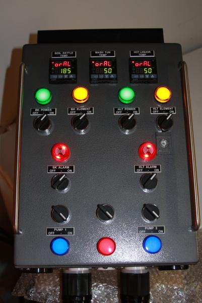
Double checked the terminals and went through a full bench test. We are ready to rock!

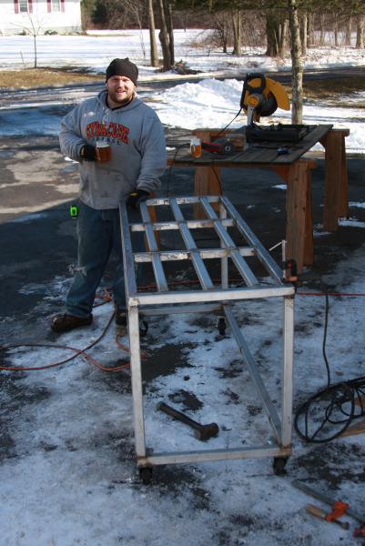
First pic is of my buddy working on our stand, changed from diamond pattern to straight linges. Looking toight!

Some amarillo IPA to keep the chill away

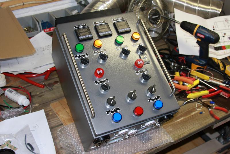
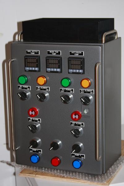
The rest are way too many pics of the completed control panel...

1.jpg


2.jpg


3.jpg


4.jpg


5.jpg
 
Will get some more shots in a few weeks-month when we wrap up our stand and get the armature all set up. I think it will be a little easier to get a good shot of it once it is in its final position.

Thanks for all the help guys. No way I could have come this far alone.
 
Back
Top