E-Brewery Build

Homebrew Talk - Beer, Wine, Mead, & Cider Brewing Discussion Forum

Help Support Homebrew Talk - Beer, Wine, Mead, & Cider Brewing Discussion Forum:

This site may earn a commission from merchant affiliate links, including eBay, Amazon, and others.

OatStraw

Well-Known Member
Joined
Aug 13, 2011
Messages
254
Reaction score
20
Location
Bartlesville
So I've decided to go electric. I've been contemplating this for a long time and been doing a TON of research. If you've seen the master thread of all of PJs diagrams I put together then you have an idea of how long I've been thinking about this.

I debated wether or not I would do HERMS or keep using the cooler system that I already had. I've decided to continue using my cooler as the Mash Tun since it's been working and I haven't had any issues with losing temperature.
THfYF1el.jpg
[/IMG]

Both of the Keggles will be converted to run 5500w heating elements. These are in the mail and I will receive them today.

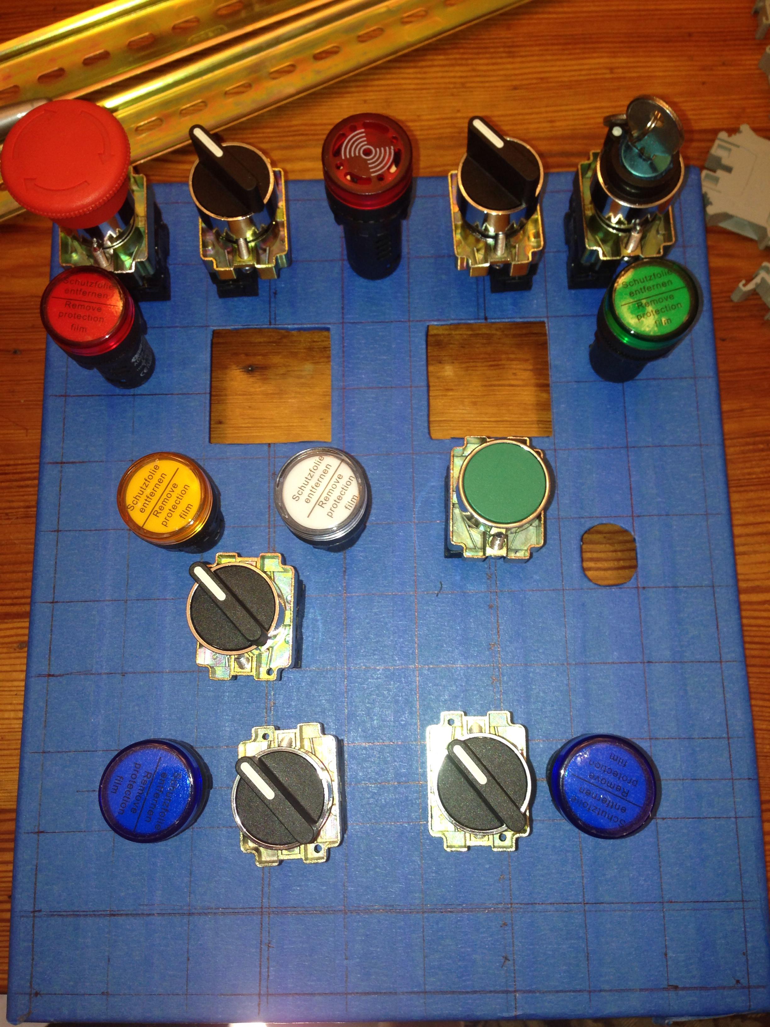
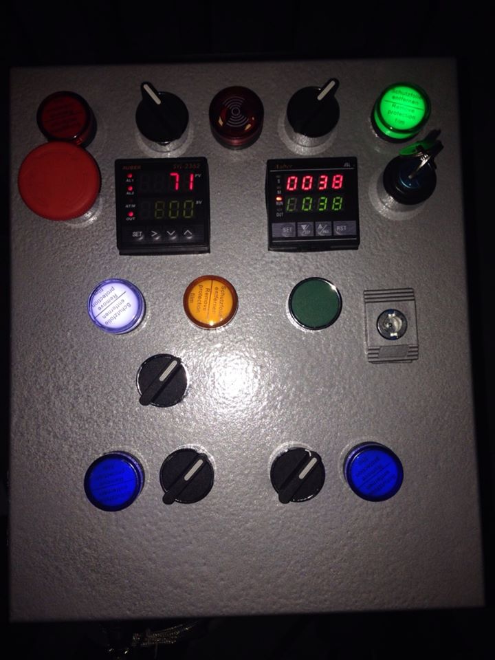
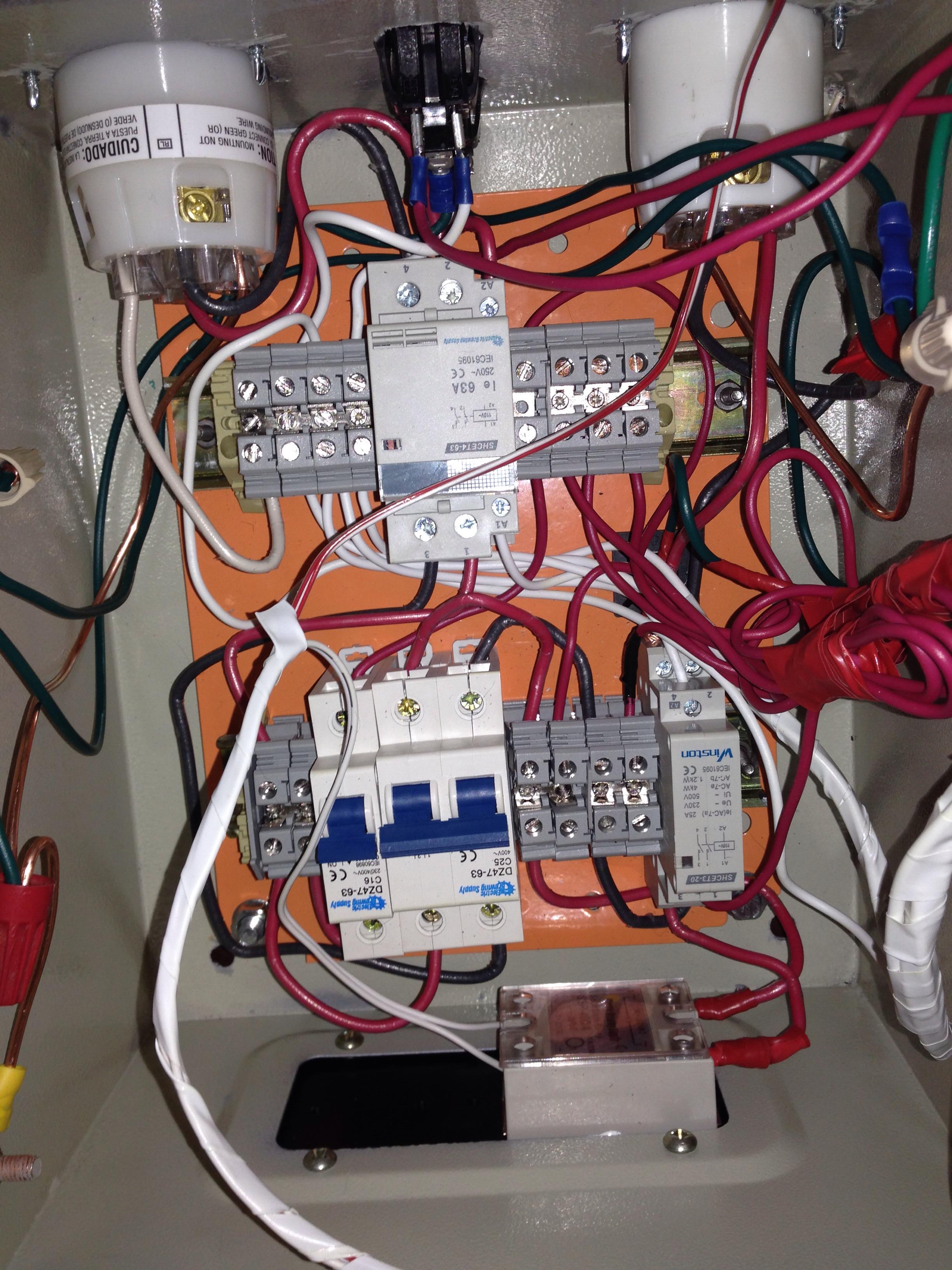
For the control panel I decided to go with ebrewsupply.com and purchase their 30A eBIAB kit. Since I won't be doing a recirculating mash I have no need for 2 PIDs, and do not need to be able to have both elements plugged in at the same time (especially since on 30A they can't both run at the same time). So this BIAB kit is perfect for my needs, all I will have to do is switch which element is plugged in and put the PID into manual mode for the boil. Won't even need a 2nd temperature probe.

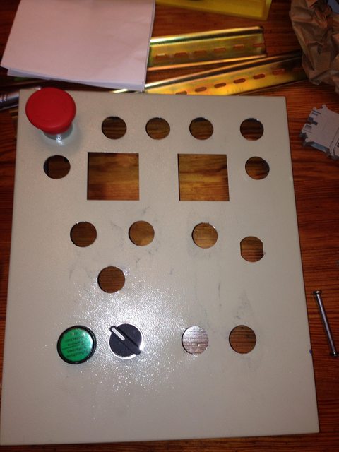
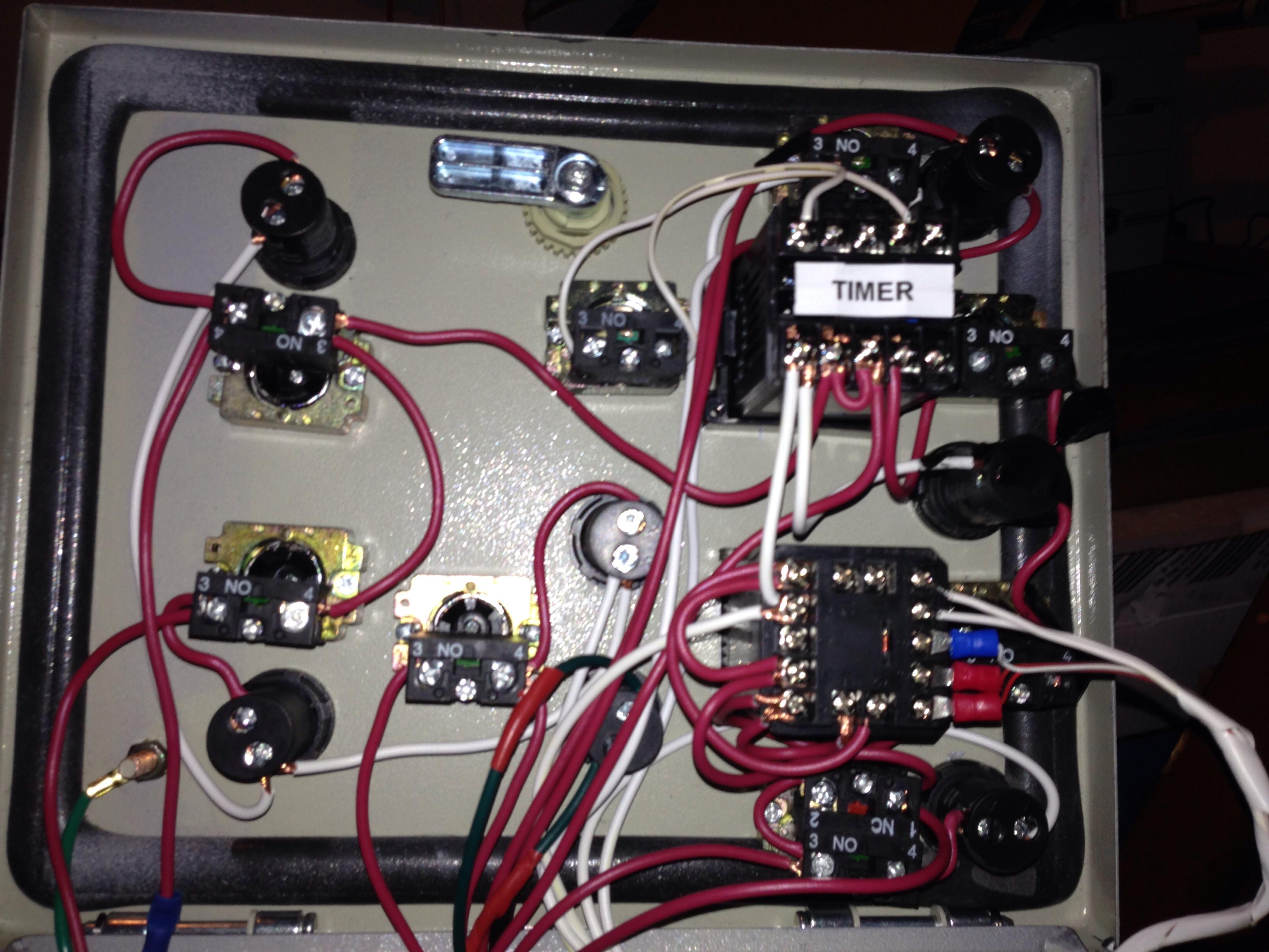
I'm still playing with the panel layout, and will have to order the buzzer (pictured as the red circle) and a reset button.

5TBHdaql.jpg
[/IMG]

I will post a list of where I got all my materials tonight. One assumption I made early on was that making one of these control panels would be cheaper than buying High Gravity's EBC SV. I think it will be REALLY close.

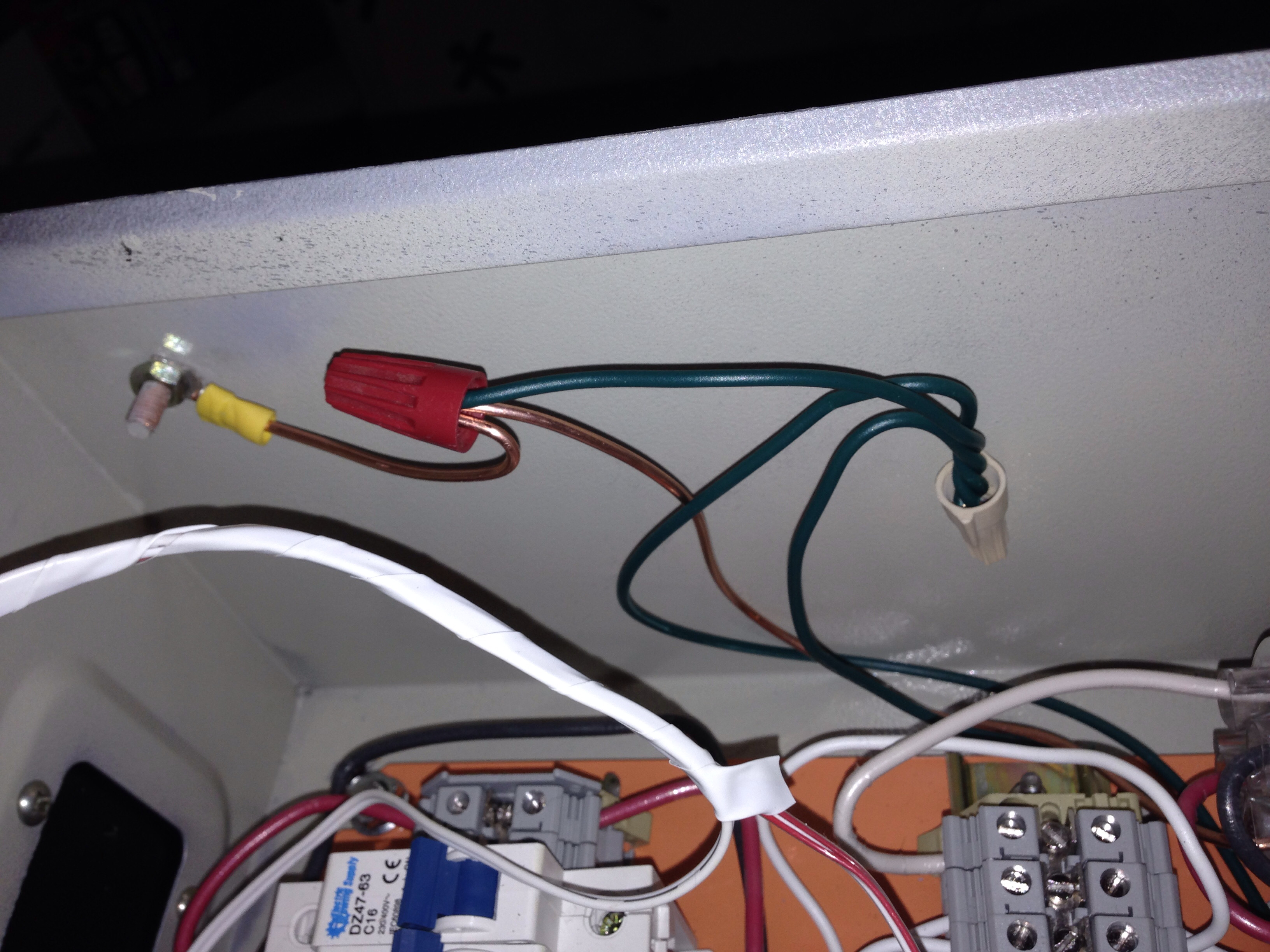
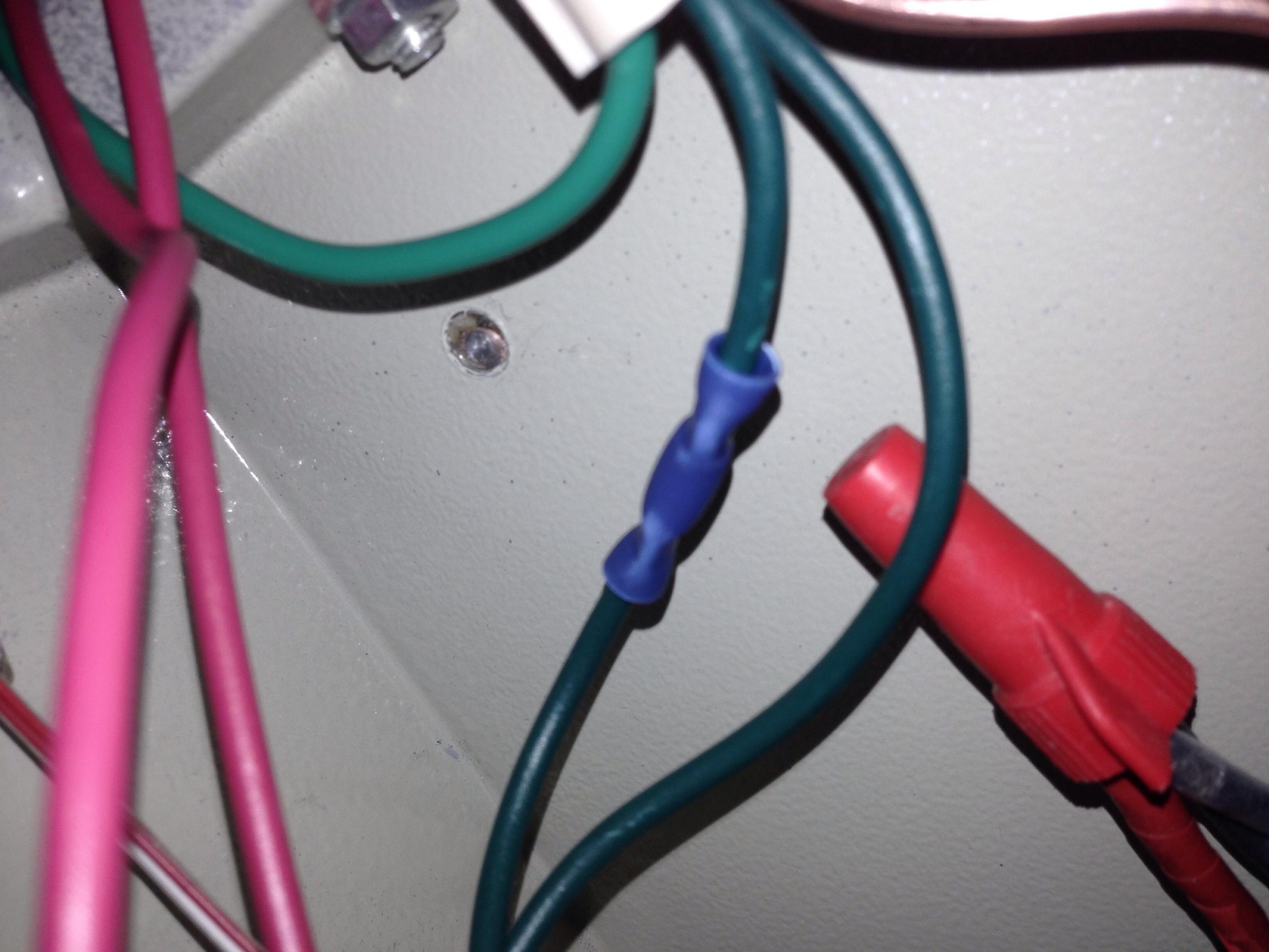
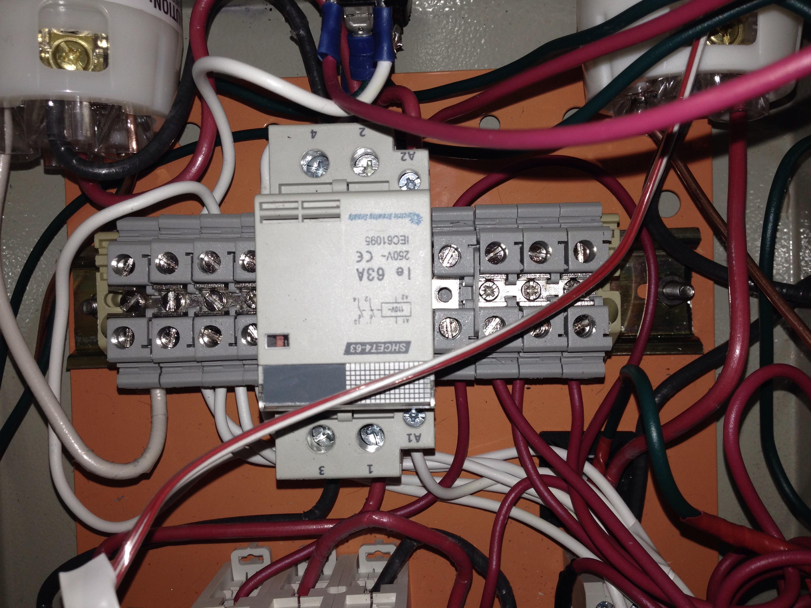
One area that I am kind of nervous about is the wiring. The kit came with DIN rails and DIN rail terminal blocks (with all the accessories). I have no idea how these work or interact with each other, so if you know of any builds that have used these please let me know!
 
Looks good so far! We'd have to get a picture of your DIN rail terminals to give you an idea of how they are supposed to work with each other.
 
You can see how the din rails work if you have a look at my build. The terminal blocks are tied together internally (each side of the block is directly connected) but you do need to bridge to adjacent blocks using the accessory bag. You'll find some silver bars in there that screw into the top of each block allowing you to tie groups of blocks together. If you only need a few, simply shorten the bridge.

Example inside of mine:

Close up of the terminal blocks, tied together:
ebrewery_93.jpg


Be sure to use the terminal block seperators between dissimilar legs.

Overall din component installation:
panel_05.jpg
 
...

If I put a wire in on one side of the terminal, does the other side get energized, or are they independent?

Yes, that is correct. Each grey block is connected through the block with a conductive bar. If you hook a wire to one side of a single block, the other side (with the screw down) will be energized. To tie multiple blocks that are adjacent together, you use the bridges as I detailed.
 
OK That makes sense. If you need a bridge to tie multiple blocks, then what is the purpose of the terminal separators?

Sorry for the newb questions, just want to make sure I'm using these correctly as the consequences could be shocking!
 
OK That makes sense. If you need a bridge to tie multiple blocks, then what is the purpose of the terminal separators?

Sorry for the newb questions, just want to make sure I'm using these correctly as the consequences could be shocking!

Let's say you wanted one main black (hot) wire to be split into four black wire circuits so you can power different stuff in your control panel and four white (neutral) wire circuits to flow back into the one main white wire that goes back to your house power supply.

So you'd take four terminal blocks and electrically tie them together with the metal strip thing that runs through the middle, and then you'd take your one wire and screw that down and then take the four wires and screw them down, and then they'd all be electrically bonded together. And then you'd do the same with the other color. And then you'd put a separator between the two sets to make sure that they don't accidentally make an electrical connection. Or just put some air space between the two sets.
 
So the separator is just a safe guard to protect against a chance of an arc occuring? It's not actually cutting something off.
 
Decided to add a buzzer and a physical reset switch for the time. Here is the new layout.
xABOTdY.jpg


I'll be drilling this afternoon and finding some paint.
 
Got all the drilling done on the lid and all the holes cut for the plugs on the box. I still need to drill the mounting screw holes, anyone know what size these should be?

4o5u0rSl.jpg


I am going to sand and paint tonight then hope to start wiring tomorrow. Thinking about a Silver lid with a Purple box (K-State fan).
 
I decided to paint it hammered silver.
OAmufqi.jpg


Will begin wiring it later today once this last coat dries.
 
Well I measured and drew the plan for cutting my panel lid with the box enclosure in mind. However I did not take into account how much larger the BACK sides of the switches are and measured only for the diamater of the switch it self. I get to now grind off some of the boxes top lip.

BpRRjdyl.jpg

Lz0bZZQl.jpg


It will close if I turn the back part of the switch to the side, but then the front part of the switch isn't vertical, and there is no way to orientate it and lock it in like this to allow the front to remain vertical.
bkTOuQu.jpg


2 lessons here.
1. Measure everything not just what's vissible.
2. Buy a larger box than you think you will need.
I made the same mistake if it makes you feel any better.
 
I have to say that Ryan at ebrewsupply.com is the best. Dude has helped me so much and will respond to all my dumb question with patience and clear instructions. Don't hesitate to work with him. Great vendor.
 
+1 on ebrewsupply (Ryan) - he sorted out an issue with my order parts with no hassle at all. Great guy.


On the box and switch mounting, I *almost* made this exact mistake. Before I cut i laid out the inner lip in pencil and caught it. I ended up shifting the whole upper row accordingly as you also need room for the crimp terminals when screwed into the switch.


Sent from my iPhone using Home Brew
 
All done and wired up.

CJjWEPF.jpg


Does anyone have a good write up on the settings I should use for the Auber 2362? Planning on doing the Auto Tune, but need to make sure I have it set to the correct heat and alarm settings first.
 
Yeah I think Kals is based on the 2352 which had completely different menus and setting parameters.


I've been reading Aubers instruction manual, but I'm lost in translation lol.

Yes, you are correct, I overlooked the model number that you listed!
 
Nice work on the panel. I'm building mine with the same box. Because I saw your post about clearance with the inside of the box, I avoided that issue. But I neglected to account for the grounding stud on the door. Because there's a second grounding stud on the inside, I just ground off the one that was "in the way." So far it's coming together; next up is actually wiring it. I'm still waiting on my cable glands and a buzzer. I may decide to paint the box while I wait.
 
@Woodbrews.

Since you only have 1 grounding stud to work with now be VERY careful on how tight you put that nut on. I over tightened on one of the studs and it broke off, luckily there was the 2nd one in the box.

Looking back I wish I would have gotten a larger box, but the convenience of having those two DIN holes already cut was really nice.

Wire EVERYTHING before you put it into the box. Then put the door and bottom plate on at the same time. The only hard part was then wiring the 10g wire into the board from the output/input sockets. I will take a picture of the inside tonight to show you how I positioned my contractors so they didn't interfere with the reciprocals.

Thanks for the heads up. A picture is worth a thousand words. How did you connect your wires to the grounding stud? It's larger in diameter than most of the spade and ring connectors I've found. And was there nut supplied for the grounding stud? I haven't opened the bag that came with the box, so perhaps it's in there.

As for the 10/3 (element) and 10/4 (power) wires, I've decided to bring them straight into the box and secure them with a cable gland, instead of using locking receptacles. The receptacles are expensive and take up a lot of interior space. For the element, I found a 10/3 extension cord that I'll cut. I'll use the male end for the element and the female end as a pigtail coming out of the box. The extension cord was cheaper than the cost of a receptacle and parts to fabricate my own cord.

Inside the box, both cords will connect to a terminal strip.
 
That's a good idea if you don't require the ability to disconnect the cables. The receptacles do take up a lot of room.

The ground posts are larger than the circular connectors so I used split spades, but it was difficult to wire multiple onto one post. I brought all my grounds to a wire nut then ran 1 wire onto the ground post.

You should have received 2 nuts in the small package.
 
Thanks, I'll check the package this evening for the nuts. One problem I ran into was not providing enough clearance for the PID. It protrudes so far into the box that it really limits what you can mount on the backplate. I made it fit, but it will be tight with the wires on there. Another mistake I made was really dumb - I punched one too many holes on the front! I got on a roll with the conduit punch and somehow miscounted the components I needed to mount. Luckily, the fix was easy -- I purchased an alarm light. Which leads to my question -- how do you have your alarm light wired? Is it wired directly to the PID? Thanks!
 
The Alarm is wired to the PID and the Timer. I use those two switches on either side of my buzzer to turn on/off the PID or Timer alarm.

Here is the wiring diagram. I did it the exact same, except the Green 220v led is wired different and I used a different timer, so the numbers on mine were different, but same general idea.
http://www.ebrewsupply.com/designs/PID/30a-PID-1-2-1PID-Electric-BIAB.pdf
 
Alrighty. Got a lot of work done.

Drilled holes in both keggles.
LwxREpB.jpg


Had some requests for some wiring pics. With this small of an enclosure it's hard to make "nice'wiring runs, but I did the best I could.
JtatIgK.jpg

GSaIShC.jpg

TK2ZdSC.jpg


This is where I tightened the nut to the post too much and it came off.
3sQXD1j.jpg


Had to think out the lay out of the HUGE contactor since the input would have hit it.
SgUK46m.jpg
 
All of those green ground wires should be "home runs." IE - wires that run directly to the box, and then that box connection runs directly to the main ground wire.
 
Yes all wires connect to the box and the lid as well. The box is then connected to the power input ground which runs back to a gfci protected outlet.


Sent from my iPhone using Home Brew
 
Lando can correct me if I'm wrong but I think he means there should be no splicing of ground wires. The wire should run from its source uninterrupted to the grounding post. I think if you look through hunter's build thread there are some really good pix of how he did it.
 
Hmmm. Not sure I understand the need. Grounds are shared all the time.


Sent from my iPhone using Home Brew
 
Just checked some electrical codes and it's fine as I'm using 10g for the shared.


Sent from my iPhone using Home Brew
 
Just checked some electrical codes and it's fine as I'm using 10g for the shared.

Sent from my iPhone using Home Brew

Just run all of the ground wires to the bolt on the box. That's all you have to do. You don't want that wire nut coming loose and then only part of the circuits being grounded. No, it's not likely to happen, but why bother taking the chance?
 
Planning on installing the elements today and leak testing. Hope all goes well.

I'll be using brewhardware.com enclosures.


Sent from my iPhone using Home Brew
 
Back
Top