CraftBeerPi - Raspberry Pi Software

Homebrew Talk - Beer, Wine, Mead, & Cider Brewing Discussion Forum

Help Support Homebrew Talk - Beer, Wine, Mead, & Cider Brewing Discussion Forum:

This site may earn a commission from merchant affiliate links, including eBay, Amazon, and others.
I'm not sure how your temp probes are wired, but after a lot of experimentation and discussion on the FB page with EEs, we've found that this is a much more stable way to wire them.

View attachment 555599

Notice how the Data pin is still jumpered to 3.3 via a 4.7k (or 3.3k) resistor while the positive power lead is now sent to 5v. Also, try to keep all low voltage as far away from the high voltage as possible. If you need to cross wires, try to cross them at a 90* angle.


Super-dumb question, but what are the gray rectangles with orange wires
 
So, I've been banging my head against the wall on this one for a few days. I'm trying to wire up my brewery controller, which will manage my electrical heating elements during the brewing process, and the issue is I am getting ~240V flowing through both my HLT and Boil receptacles. I have an SSR in between both, which a Raspberry Pi 3 is supposed to control. Regardless whether the SSRs are enabled or disabled, ~240V continues to flow from Power In through the HLT and Boil receptacles. Can't figure this one out, but I'm sure someone out there will point me in the right direction.

Thanks,

David
Are you seeing this voltage only before the Raspberry Pi is fully booted up and then it stops? If so, I think that the lower number of GPIO pins (maybe 2-8?) are activated high until the Pi finishes booting. I've seen a recent post on the forum about that.

Or, if you don't have a load on the receptacles, maybe it's just leakage through the SSR and not really anything to worry about? I think I've seen that if there's no load, you may be able to measure voltage leaking , but once a load is applied, it'll drop down to zero and not an issue.

Those are my guesses.
 
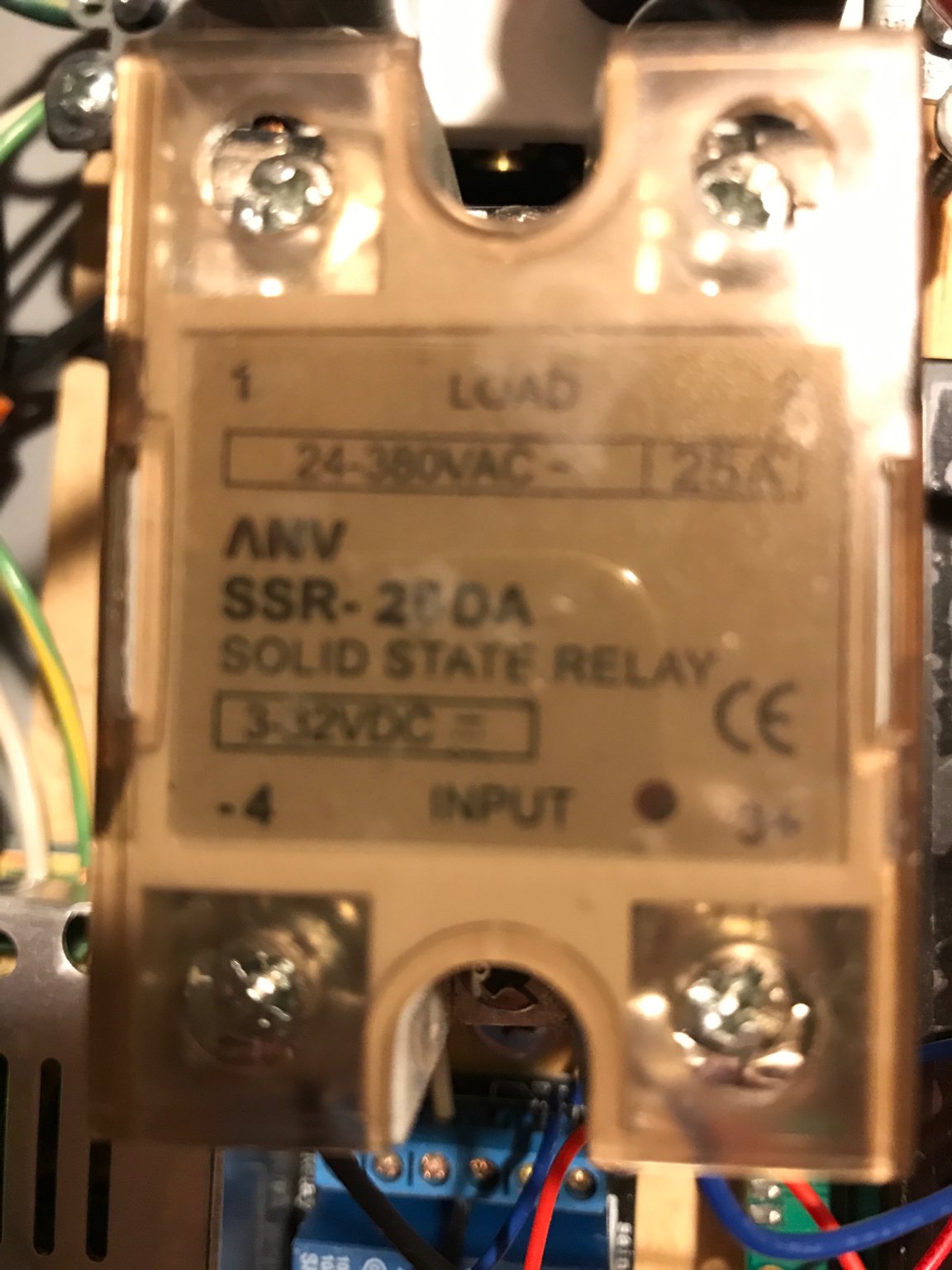
I would post your exact model of SSR, and/or a picture... (1)The SSR may not fire on 3.3V that the GPIO puts out, you may need an SSR that triggers on the lower voltage more reliably, or (2)You may need a transistor to level shift the signal to 5v from 3.3v(this is what the teragaddy boards do.)

My plan if this is needed with my SSR's is to disconnect a relay from the relay board, and put header pins where the relay coil terminals were, this lets me rob a single relay channel of an 8 channel board to drive the SSR...

That is an interesting tip. The SSR is rated from 3-32 volts. I tested it as follows:

  • Straight off 5v power: led illuminates and SSR powers the heating element
  • Straight off 3.3V pin on breakout board: led illumiates (dimly) and SSR powers the heating element
  • Off of GPIO5 when set to "heat" by CrafteBeerPI: led does NOT illuminate and SSR does not provide AC voltage.
I have plenty of the transistors left from putting my Terragady board together. What do I need to do to level shift up to 5v?

I'm actually running a 2 channel relay board. I suppose I could use the second one to deliver 5v to the SSR. I was planning on keeping the SSR direct so it didn't stress a relay if it short cycles to control temperature.

Still thinking I have something set wrong since I can get it to work off of 3.3v, but I can't seem to get 3.3v at the GPIO pins that I need.
 
@clearwaterbrewer: I never had my element plugged in, as I wanted to test each receptacle individually. Does the circuit need to be complete for the SSR to function properly? Having read your reply I wired up my element and sure enough it won't active until I enable the SSR. Once I added the element to the equation I am not seeing voltage on the HLT receptacle nor the HLT element until after I activate the HLT actor in CraftBeerPi.

@rkhanso: I have not measured voltage with the Pi powered off, but that will be my next test. The load has been on for Power In, but now I'm suspecting the HLT receptacle is showing voltage because the circuit was not completed prior to @clearwaterbrewer's reply.
 
Those are simply connectors, like a junction box function. They show that those connectors are tied together. How you choose to do it is up to you.
Ok thanks. So then best practice would be to tie those connectors together with a ...?
 
I use a "4 Channel IIC I2C Logic Level Converter Bi-Directional Module 3.3v to 5v board" to raise the voltage to 5v.
You can purchase them for less than a dollar shipped by slow boat or pay a shipped from the states one for a couple of bucks.

Something like this I use:

images.jpg
 
@clearwaterbrewer: I never had my element plugged in, as I wanted to test each receptacle individually. Does the circuit need to be complete for the SSR to function properly? Having read your reply I wired up my element and sure enough it won't active until I enable the SSR. Once I added the element to the equation I am not seeing voltage on the HLT receptacle nor the HLT element until after I activate the HLT actor in CraftBeerPi.

That is normal operation...
 
That is an interesting tip. The SSR is rated from 3-32 volts. I tested it as follows:
I have plenty of the transistors left from putting my Terragady board together. What do I need to do to level shift up to 5v?

have a look at post 1051, you can wire up a transistor, diode, and 1k resistor to do it... note that the +12 will be +5, and is OK... also, you may be able to get creative and put it all in a piece of heatshrink with input wires coming out one side and outputs coming out the other...
 
I will have to sit down and scratch my head a bit to see if I can figure out how to make the very clear diagram match the little metal and plastic bits I have. lol

In the mean time I hooked it up to the other relay I have so that the relay is driving the ssr with a full 5 volts. That worked a charm.

Now I just have to figure out the flaky DS18B20 sensors and I think I will at least be operational. I'll do some more poking around this week with some extra sensors I have. See if I can diagnose what is going wrong.
 
Auber SSRs work fine on 3.3v. Fotec version I had did not. Driving an SSR with a relay is sub optimal. And Rube Golderg....
 
Yeah, I’ve got to figure out why my SSR isn’t working. For now the relay got me running. It’s not a long term solution for me.

The brand is ANV.
IMG_1517883307.586683.jpg


Looks like my temp probe problem is due to my homemade probe. I did a rock solid job of shrink wrapping the connections, but I’m guessing in the tough environment of the RIMS tube and the connections degraded. I also didn’t understand back then that flux can have long term detrimental affects on connections.

I rebuilt the probe with a new probe. Cleaned the connections after soldering, shrink wrapped the individual leads, sealed them with sealant, then shrink wrapped the whole lot right up to the probe and then sealant on those ends as well.

I’ll install that in the stainless thermowell tomorrow and test it out.
 
Yeah, I’ve got to figure out why my SSR isn’t working. For now the relay got me running. It’s not a long term solution for me.

Krydom SSRs for the win. Even used ones are quality. You won’t be sorry.
 
Yeah, I’ve got to figure out why my SSR isn’t working. For now the relay got me running. It’s not a long term solution for me.

The brand is ANV.View attachment 556805

don't recognize it, you could get a different one, but making a transistor/resistor 'dongle in a heat-shrink tube' would definitely fix it...


Lay the transistor flat side down, with pins pointing to the left:
- Solder/crimp the 1K ohm resistor to the center pin (pin 2, base) and solder a wire with female pin connector to the resistor
- connect to GPIO
- heat shrink it​
- Solder the top pin(emitter, pin with arrow, pin 3) to a piece of wire with a female pin connector.
- heat shrink it
- connect to GND on Pi​
- Solder the bottom pin(collector, pin 1) to the non-stripe end of the diode *and* to a wire with a male pin connector
- heat shrink it (this one should be heat shrinked before next step)
- connect to - on SSR​
- Solder the stripe end of the diode *and* to the middle of a wire with a male pin connector one one end and a female on the other
- heat shrink it
+5v on Pi(female end) and + on SSR(male end)​
- heat shrink the whole thing with adhesive lined 8mm heat shrink...​

EDIT: mark your wires or document the connections by color, and write them down somewhere or take a pic before heatshrinking!!!!
 
Last edited:
Awesome instructions clearwaterbrewer! Thank you for breaking it down for me. That is above and beyond the call of duty!

Hopefully I'll get a chance to give it a shot this weekend.
 
And here is a Pi ZeroW with direct wiring to temp sensors with a 4.7k 'one_wire dongle', direct wiring to a relay board, and direct wiring with the 'SSR-dongle'... all works perfect with CBP... now to design it to use multi-pin housings, a bulkhead connector for the temp probes, and maybe find a 2x20pin housing for a complete wiring harness for my production installation with the Pi 3b, it would be nice to get a ribbon cable with a bit thicker wires, that way the cover can go on the 3b... Yes, in production, I will use a real power supply, not the USB cable, but this testbed works fine with it...

IMG_20180208_132848.jpg
 
Ok thanks. So then best practice would be to tie those connectors together with a ...?
I used a Terragady 4.2 board, which already has them tied together.
-or-
I suppose it sort of matters what gauge wire you're using. I am using Ethernet cable for my temp probes. If you're using something that small, you could use ScotchLoc or similar connector, some sort of buss-type connector. Even soldering them together and putting some heat-shrink over it.
 
Installed Craftbeerpi twice and still not running. I get "is not running...failed!" after I run it and then check status. Anything else to try? Thanks!

UPDATE: Found a solution that worked for me. I loaded a fresh new download of software onto a different Sandisk card. First a complete new install of NOOBS from Raspberrypi.org, then a fresh new install of Craftbeerpi. After reboot, the thing seems to work just fine as I view it from my browser. I chose to have Craftbeerpi load on start up.
 
Last edited:
Is there a way to stop running Craftbeerpi without shutting the Raspberry PI down? The two options on the "About" tab are to restart or shutdown. Shutdown shuts the PI down. I would like to simply stop the program from running and leave the PI booted up. [Set up remotely and operated via wifi on desktop or from iPhone, with no monitor or keyboard hooked to PI.]
 
Is there a way to stop running Craftbeerpi without shutting the Raspberry PI down? The two options on the "About" tab are to restart or shutdown. Shutdown shuts the PI down. I would like to simply stop the program from running and leave the PI booted up. [Set up remotely and operated via wifi on desktop or from iPhone, with no monitor or keyboard hooked to PI.]


Shell Commands to controll the Server:

- Start: sudo /etc/init.d/craftbeerpiboot start
- Status: sudo /etc/init.d/craftbeerpiboot status
- Stop: sudo /etc/init.d/craftbeerpiboot stop
 
Last edited:
I'm happy to report I had a successful first brew day with my Craftbeer Pi! Thank you to all those who helped me troubleshoot.

To those that were following along, I had a number of problems. My Terragady board was backfeeding 12v into my Pi. I ended up taking off the voltage converter and jumping across the terminals to make the whole board run on 5v. (I'm guessing this was caused by me not assembling the board well, but I have not been able to find a fault.) I also needed to get a larger power supply to run the whole system. I picked up a 5A LED power supply and that seems to be doing the trick. I suspect it is still overkill, but the small 2A wall wort was causing the Pi to show the voltage icon. Lastly, I had purchased a whole bag of cheap DS18B20 chips a while back. It turns out that out of the 10 two were functional, and one that was working for two years gave up just as I was switching to this new Pi system. Very frustrating, but a new DS18B20 was purchased and fabricated into a long stainless probe for my RIMS tube. For those of you who are new to electronics, something I learned since I put together my first probe is that cleaning the flux off the connections can help in longevity. Apparently some flux will degrade the metal over time.

Thanks again to all those who offer their help here. It allows someone like me who only knows enough to be dangerous to put something like this together. Now, to get it all out of the prototype stage and install it in an enclosure!
 
When trying to connect, I get "Connection refused." Hadn't had that problem before.

UPDATE: Found some helpful info here: https://www.raspberrypi.org/documentation/remote-access/ssh/

Sorry, should have been more specific...
I run those commands from a command prompt using the program Putty to SHH into my PI on my home networked computer.
I'm pretty sure can enable SHH when installing NOOBS, just tick the box.
To shortcut things, I have my PI setup on a static IP address so any browser or Putty on my home network I just click and connect... the address always stays the same.
Once you have SHH working you can change other Pi settings in a GUI by running from the prompt .... sudo raspi-config
Cheers
 
Hi, i have a problem whith my CBPi. After instalation and configuration my CBPi working inversely i would like. When i turn on my rpi and system start up, all SSR relay turn on, in the CBPi web site look like of. When I click on the heaters button and it lights up in green then SSR relay turn off. What may be a problem?
 
your problem is very common. you need to configure the actors differently. If you have them set up as GPIO, then set them to 'relay board', if you have them added as 'relayboard', then set them as GPIO. This happens because some relay boards activate the relay on a +5v signal, and some activate on a gnd signal... also, you may see GPIO 5 and 6 be on during startup, this is just he way that rPi is designed.
 
Hi guys,

I'm preparing to build my automated electric brewery with CraftBeerPi. Does anyone know if there is a configuration on CrafBeerPi that avoids more than 1 heating element to be on at the same time?

Thank you.
 
Building with craftbeerpi3. Very cool tiltpi integration! Is there any documentation on setting up basic brewing sessions? I'm trying to get heater to turn on and maintain temp at 153. I can't figure out how to have temp voltage vary to maintain temp. All help appreciated.
 
I got my raspberry pi up and running but there is no chart under fermentation. I looked for the log under /home/pi/craftbeerpi/log but could not find it. I am using version 3.
 
I got my raspberry pi up and running but there is no chart under fermentation. I looked for the log under /home/pi/craftbeerpi/log but could not find it. I am using version 3.
So I discovered that version 3 is under its own directory. log files are under /craftbeerpi3/logs directory instead of /craftbeerpi/logs
 
Brand new on CraftbeerPi and having an issue. Set it up to control fermenter.
First test seemed to work ok, temperature reading ok, heater relay functioning.

My problem is after setting up fermentation steps, it won't advance to the next step.
Once it reaches target temperature in step one, the timer starts and counts down. Once the timer reaches zero, it doesn't record an end time and never starts the next step.

Am I missing something in the setup?

I haven't been able to find anything on this problem when I search so it must be working for everyone else.
I am running v2.2 right now.

I tried v3.0 but it wouldn't work at all.
 
Loving Craftbeer Pi so far! Can anyone tell me if there is a way to make it start the next step automatically? I want to be able to reach a target temp and then have it automatically turn down the temp using PWM. Or even have it fire up a pump without any additional input.
 
I have my cbpi3 box all set up everything seems to be right on the hardware side, my problem is I can't seem to get it to control my heaters. I setup up a mash-in and a few mash steps and then a boil step. When I run it run as it should but will not turn on and control my heaters (the buttons don't light up green so it's the software not wiring). Is this working in 3.0?
 
I have the answer to my own question. Should any newbies (like me) need to, you can add self.next() to the end of a step and it will continue to the next one. Super handy!!!
 
What I would be interest in is knowing is how to create a recipe for perpetuity. I have come up with some ideas, but I can only seem to keep one set of steps loaded. If this has been covered, I apologize and would appreciate the link to the conversation. Thanks in advance!
 
Back
Top