CraftBeerPi - Raspberry Pi Software

Homebrew Talk - Beer, Wine, Mead, & Cider Brewing Discussion Forum

Help Support Homebrew Talk - Beer, Wine, Mead, & Cider Brewing Discussion Forum:

This site may earn a commission from merchant affiliate links, including eBay, Amazon, and others.
sure, just some minor layout work, changed the 3 pin screw down terminals from the 5mm to 2mm for continuity, drill holes for the board to interact directly with the pi, clarified some text, etc. changed pin configuration and just gave the board a little more breathing room.
 
Full Kits for the 40 pin board are 20USD not including shipping. this includes everything including MP1584EN. The 26 pin board is 15.00 as a full kit.
 
How much for shipping to Norway?
What's included? What do I need to add to it to get everything up and running?
 
you need solder and a soldering iron... and some patience. i'll get you a price and PM.
 
Yes. I got that. And SSR etc. But what does it do? 5v for SSR. Connection for temp sensors, SSR, etc?

Great.
 
i'm confused about what you're confused about... screw down terminal for sensors, 12VDC switching for outputs to SSR (so you an actuate them)... you'll need a 12VDC power supply and a RASPI3.
 
I just couldn't find any specs on what was included. Just the board or components too.
 
The kit includes everything you will need to put one of my boards together. It's up to you to do the rest
 
In order (I think) of interest:
Bigdaddyale 1x26, 2x40 board only
Rtl 1x26 kit, 1x40kit
Stealth 2x40kit
Kiwirob 2x40 kit
Hellyno 1x40 kit
Alt 1x26kit, 1x40 kit
Sverd 1x40 kit
Cotton club 1x40 kit


Depending on the number of actual boards I receive, I will ship down the line and place a second order. Lemme know if I missed anyone, please pm me your email address and confirmation that what I have in the post is what you want.

Cheers!
 
Full Kits for the 40 pin board are 20USD not including shipping. this includes everything including MP1584EN. The 26 pin board is 15.00 as a full kit.

I'll take one board and one kit, both 40 pin.

Let me know what I need to do to make it happen.
 
At this point it looks like I'll have to run a second round of boards. As soon as I get boards out I'll be sending PayPal requests. Etc.
 
The boards are essentially agnostic in that regard; the outputs can be used for a multitude of purposes that can accept 12v input, except of course for the 1-wire inputs. From what I can tell having run the software only in demo mode so far, is that you could use it to control a burner with a solenoid; however, you would want to use the temperature overshoot mode for on/off control and not PID mode. Most importantly, you would need to handle flame/flameout detection on your hardware side. As far as I can tell there is no functionality in the software to monitor and react to that, at least not in CBP version 2.1. Don't know if Manuel is planning to add that to 2.2 or a future version or not.
 
The other option for burner control would be customized Python code that handles the solenoid lockout logic based on input from a 1-wire temp sensor. See the CBP Github pages (Branch: Dev2.2) for very basic guidance on how to add a custom logic. You might also want to ask on the CBP Facebook page if anyone has already written a custom burner logic that they would be willing to share - sorry, I don't do Facebook. :rolleyes:
 
Thanks again Alt, I will check it out. Facebook does nothing for me, except maybe in cases you are describing :)
 
Hi,

I've managed to set it up to the point where its reading temperature correctly on the web interface, however I Can't get the relays to activate when I start up a mash. Is there any list of common mistakes at this point? I've tried setting the heater and agitator to all available GPIOs in the settings but still nothing happens.
Can you flip the relays by manually hitting the buttons on the dashboard (or by using a python script)? Are your heaters set to auto (the car icon)? Are you using pin position or GPIO numbers to indicate your GPOI to relay mapping?
 
Can you flip the relays by manually hitting the buttons on the dashboard (or by using a python script)? Are your heaters set to auto (the car icon)? Are you using pin position or GPIO numbers to indicate your GPOI to relay mapping?

Thanks for the advice, exactly what I was looking for, I'll give these a go tonight
 
In order (I think) of interest:
Bigdaddyale 1x26, 2x40 board only
Rtl 1x26 kit, 1x40kit
Stealth 2x40kit
Kiwirob 2x40 kit
Hellyno 1x40 kit
Alt 1x26kit, 1x40 kit
Sverd 1x40 kit
Cotton club 1x40 kit


Depending on the number of actual boards I receive, I will ship down the line and place a second order. Lemme know if I missed anyone, please pm me your email address and confirmation that what I have in the post is what you want.

Cheers!

If you don't have enough boards, I would consider changing my order to 1x40 kit and a 1x26 kit.
 
I started playing with dev2.2 and I'm having trouble getting the temp to read F. Any one else having issues with it displaying C values even though it's set to F?
 
Thanks for the advice, exactly what I was looking for, I'll give these a go tonight

The car button worked, so simple! Well it worked for the heater, that's gpio 17, I thought the agitator would be on gpio 18 but that doesn't work still. To be fair I don't actually have any sort of agitator yet so this is all I need for now. Thanks!
 
The car button worked, so simple! Well it worked for the heater, that's gpio 17, I thought the agitator would be on gpio 18 but that doesn't work still. To be fair I don't actually have any sort of agitator yet so this is all I need for now. Thanks!

I don't think that 2.1 has any provision for automating pumps/agitators in the steps yet. I believe this is planned for 2.2. For now, I think you have to run those manually (through the buttons on the dashboard).
 
Is it possible to set a start time so I could have my water at just the right temp when I get in from work?
 
Any Kits left?

Interesting in one for a RPI3, for an ebiab build.. plus maybe some other automation ideas.
 
Sorry man, getting ready to do a second run before the Chinese take a month and a half off. I'll update when I have more details. Also, my first round of boards went to fab a week and a half ago with no update so... still waiting on that.
 
Can someone that's built this show some pictures of their completed system. Could someone also provide a schematic so we can see how all this wires to the pcb to the ssr's, pumps, etc?

I second this request!
I was in the middle of gathering parts based off one of P-J's wiring diagrams, the single element BIAB 30A PID when I stumbled upon this thread.

I am still very new to e-BIAB (I haven't even set up my first system), so what I'm trying to wrap my brain around is how to build the entire control box. I did see a link where someone used a PiFace, so I now have one of those. http://www.leaningman.com/2016/05/automated-brewery/

Please help me! A full wiring diagram of a control box would be amazing, if there is one floating around somewhere!

Single Element BIAB 30A PID.jpg
 
Thanks!

Are those the 240 contactors with 120 coils? The things between the SSR's and what looks like your input and output plugs?
 
Okay, so wiring the SSR and the contactor and the pumps and such would still be similar to P-J's diagram?
This is probably going to show how much of a noob I am, but is it almost like swapping out the PID in the diagram for the raspberry?
 
Sort of. You need SSRs for the pumps as well and you use the outputs of the cbpi boards to actuate the relays.
 
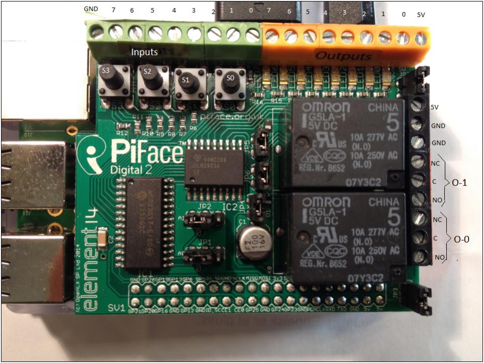
You don't need SSR's for the pumps, at least not for up to 2 pumps if you use a PiFace Digital. The purple wire to the kettle SSR in this PJ diagram posted above would connect to the 5V output (orange) terminal of the PiFace. The yellow wire to the SSR would connect to any of the eight available outputs (orange 0-7). You would eliminate switch 2 (pump) and switch 3 (PID power) from PJ's circuit. The blue wire from the 10A fast blow fuse would go to the common (C) terminal of either 10A relay (0-0 or 0-1) on the PiFace. The blue wire to the hot terminal of the NEMA 5-15 receptacle would connect to the normally open (NO) terminal of the same relay. This is in lieu of PJ's switch 2. You could, if you want, add a 120V LED for an external pump power indication. Switch 3 and the 1A fast blow fuse leading to it would be replaced by your choice of 120VAC to 5VDC (2.5A or greater) power supply with a MicroUSB plug. You would feed power to the PiFace through the MicroUSB power connector on the RasPi and connect jumper JP3 on the PiFace. Again if you want, you could include a separate 120V LED between the yellow neutral and blue hot wire leading to the 5V power supply to remind you that the panel is hot.

PiFaceDigital2.jpg
 
Thanks so much! That makes things much clearer!
I think I'm following you up until the 5V to the RasPi. I run power to the raspi and then jump from the raspi to the jp3 of the piface? What port do I use on the raspi side?

Again thanks!
 
Back
Top