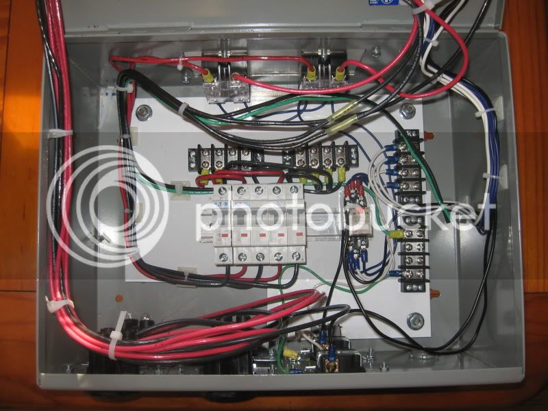
The issue that I see is how to deliver the power to the element pairs and prevent both sets being powered at the same time. With one power source that was accomplished in the last diagram. With a second PID, the power now becomes 2 sources that are independently controlled. With that said, I'm at a loss on how to interlock them. I don't believe shutting the PID down is a viable solution.P-J, would it work if I switched both PID's off switch #1 instead of feeding them from 15 15 amp CB? For emample, HLT PID power is switched on pin 10 or 4 and BK PID is switched on pin 6 or 12.
It would be far easier to use the single PID and install a second temp probe in the boil kettle. Then use a switch to swap probes as needed.


![Craft A Brew - Safale BE-256 Yeast - Fermentis - Belgian Ale Dry Yeast - For Belgian & Strong Ales - Ingredients for Home Brewing - Beer Making Supplies - [3 Pack]](https://m.media-amazon.com/images/I/51bcKEwQmWL._SL500_.jpg)