Sorry for the delay in responses, I did not have any notifications turned on.
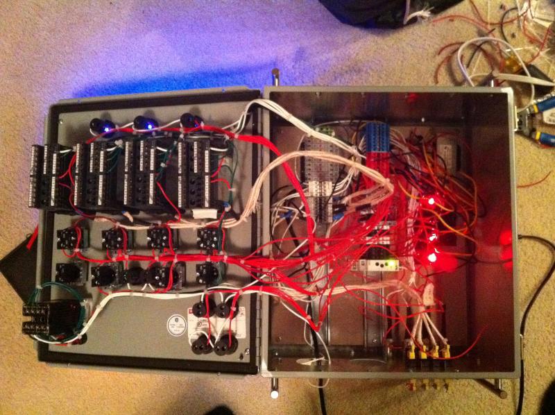
I used eurotherm controllers as I got 3 of them for free

and one from ebay for around $70. I really like them, very felxable and somewhat easy to program. I will warn you that there are a lot of configurations you can buy so make sure you are getting what you need.
So fromt he top.
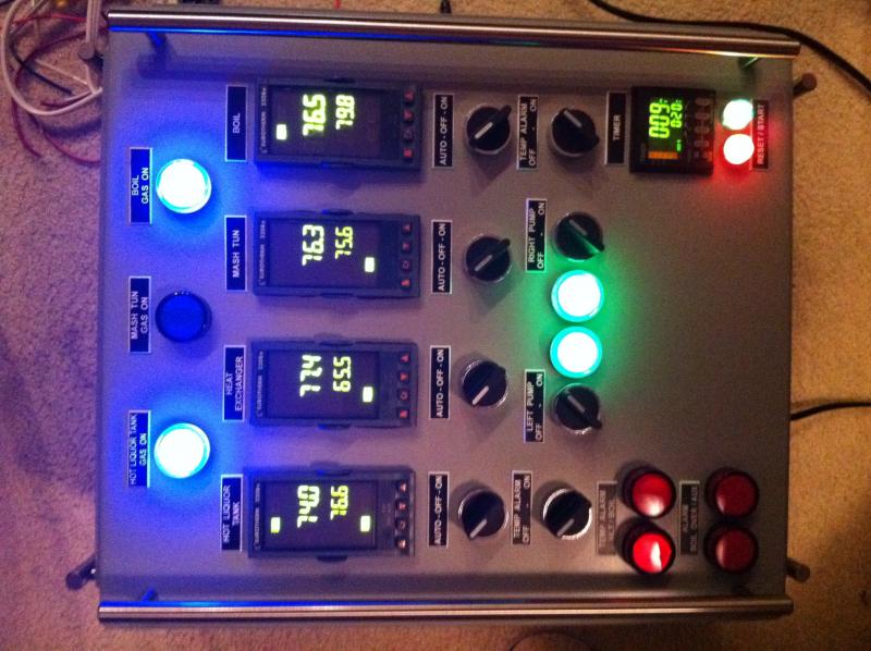
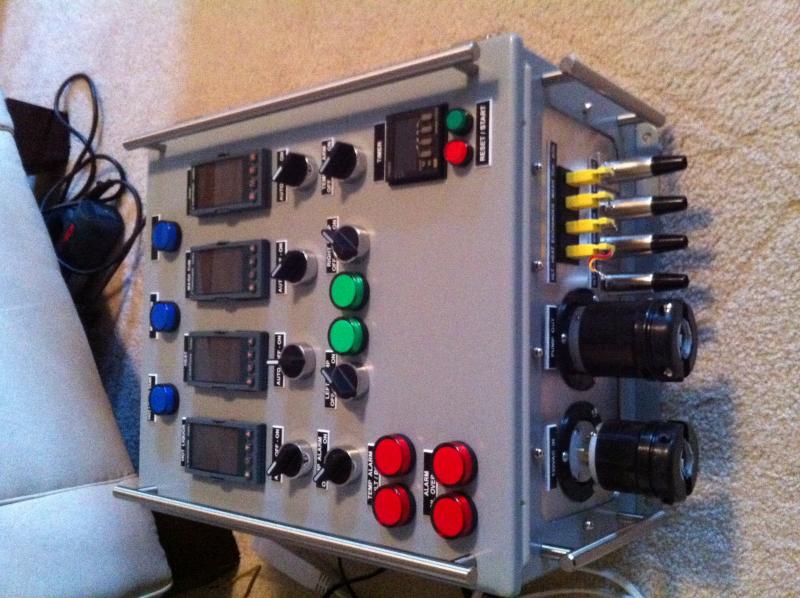
Blue lights are on when 24vac is going to the honeywell valves, so gas on for the HLT, Mash, and Boil.
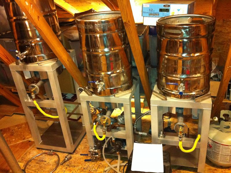
3 PIDS. Again one for the HLT, Mash, and Boil. However I added another PID for a heat exchanger in the HLT. This is a bit of a gamble. I used 50ft of coiled 316 tubing. My idea is I want to limit the gas on the Mash so I do not burn the wort. So I will be recirculting through the HTL coil. I will be monotoring the output of the heat exchanger, if its low the HTL burner will fire. If the Mash is low then the Mash burner will also fire. I have limited the mash burner by using a needle valve and putting it about 6 inches below the keggle.
Below the PIDs are some cheap 3 selection switches. Left position is Auto or PID controlled, middle shuts off the gas, right turns on the gas.
Next row down are 2 way switches. The left and right are alarms. So when the HLT or the Boil reach temp it will wake me up if I have passed out. These alarms are wired up to a buzzer and the red lights on the bottom left. The lights stay on the alarm is silenced via the switch. Middle two switches and the green lights is the left and right pump control.
Bottom right is an omega timer that is wired up to the PIDs. Thsi allows we to do a step temp if I wish. So I can set the mash to be at say 145 for 20 minutes and automatically flip to 155 for the last 30 minutes. I can also use this to do say 154, and then hit 170 to make the mash out timing more consistent.
Alarm lights. Top left is the HLT, top right is the Boil, bottom left is a boil over sensor, bottom right is an AUX that is not yet used.
Boil over sensor, you will like this one! I used a one shot relay with a variable timer on it. What the heck is that? Crap I still do not know, lol. What I have is the trigger for the relay set up on 2 wires. One wire has 24v on it. Dunk the wires in water it makes a connection and trips the relay. So my thought here is to have a 1/4 inch tubing held into the top on the keg via a compression fitting and silicone gaskets so it slides up and down. Fill the keg, more the tubing to an inch above the liquid level and done. In the tubing will be 2 18awg wires, ends of the wires will be stripped when the exit the tube and bent away from each other. I do not want a bead of condensation forming and making the circuit. The relay has 2 modes, on or off in essance. I have it inline with the 24v out to trip the honeywell valve below the boil keggle. When the relay is tripped it breaks the line to the valve for a set amount of time, aka, shuts off the gas to the boil. Rolling boil calms down, relay timer times out, gas is applied back on, and I do not have a big sticky mess everywhere.
Make sense? Now I just need to figure out how to turn on reply notifications on this forum...


![Craft A Brew - Safale S-04 Dry Yeast - Fermentis - English Ale Dry Yeast - For English and American Ales and Hard Apple Ciders - Ingredients for Home Brewing - Beer Making Supplies - [1 Pack]](https://m.media-amazon.com/images/I/41fVGNh6JfL._SL500_.jpg)


