Build my first single element panel

Homebrew Talk - Beer, Wine, Mead, & Cider Brewing Discussion Forum

Help Support Homebrew Talk - Beer, Wine, Mead, & Cider Brewing Discussion Forum:

This site may earn a commission from merchant affiliate links, including eBay, Amazon, and others.

Car Ramrod

Well-Known Member
Joined
Jan 24, 2019
Messages
117
Reaction score
16
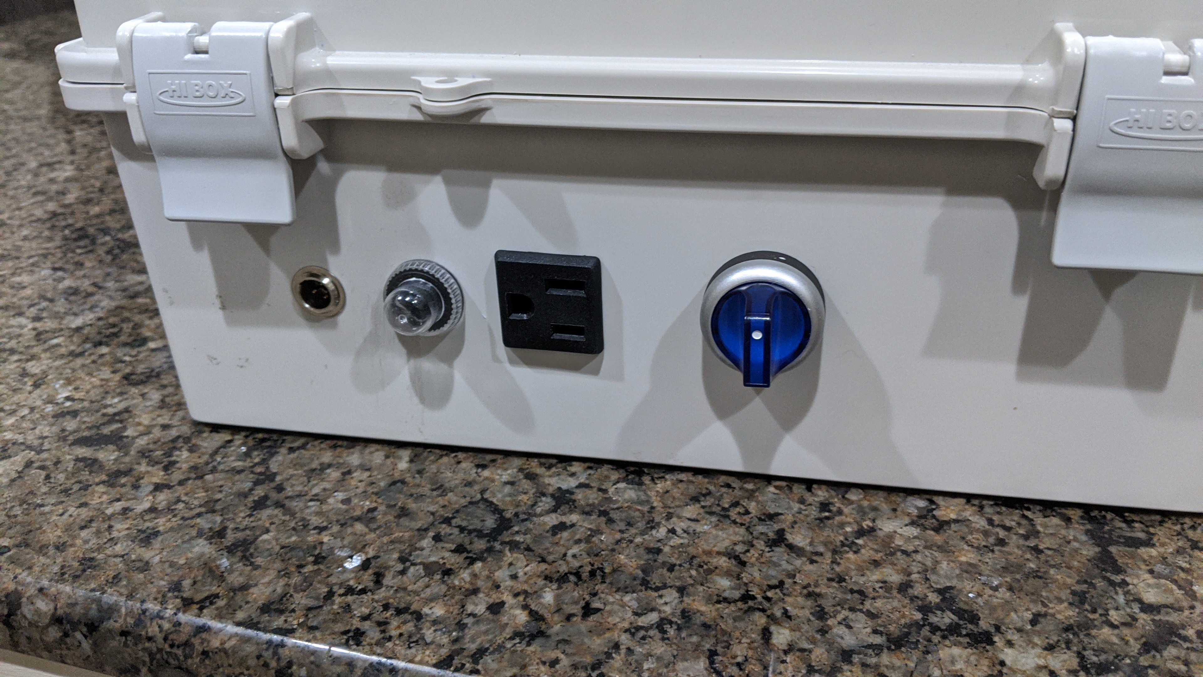
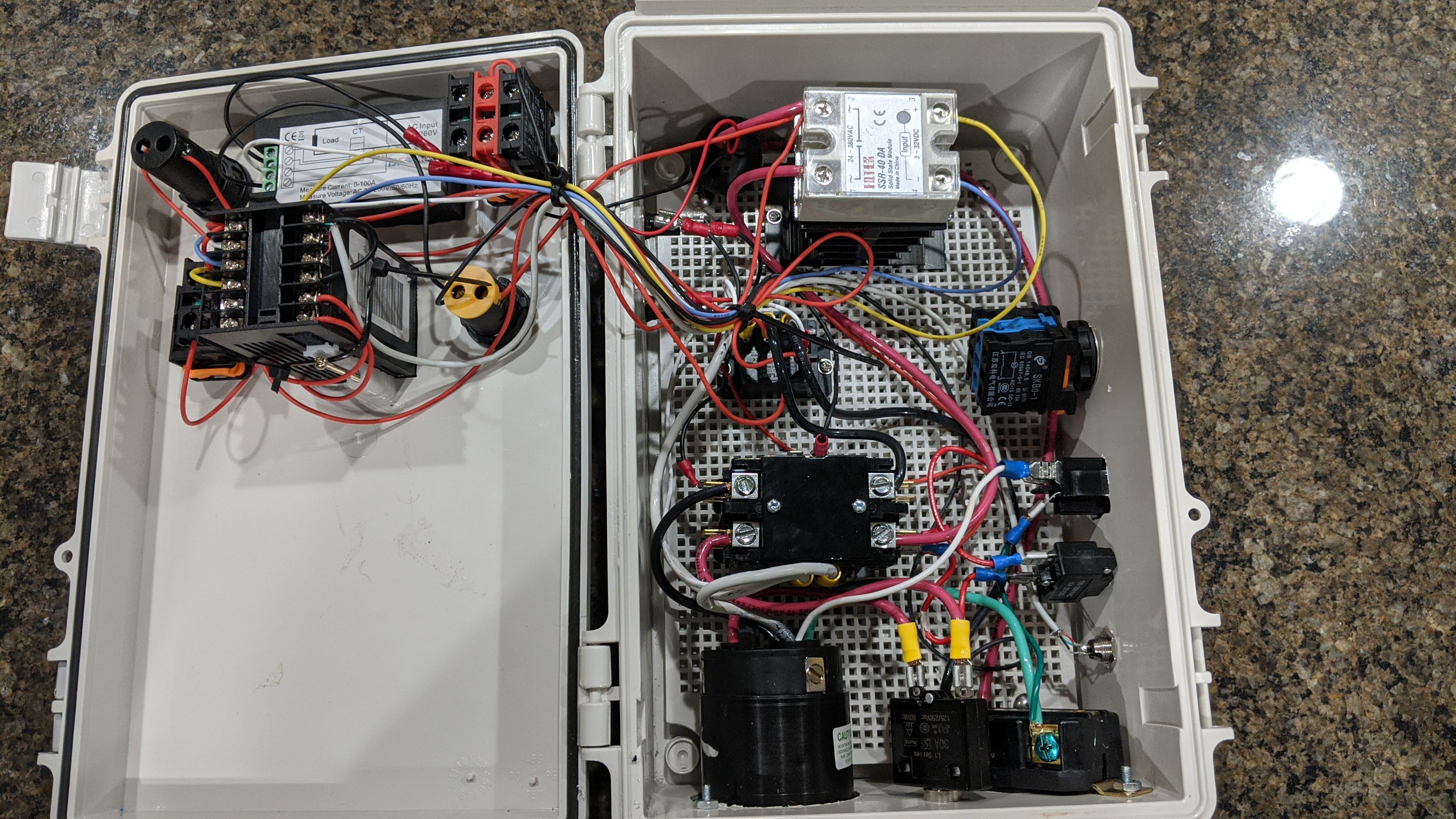
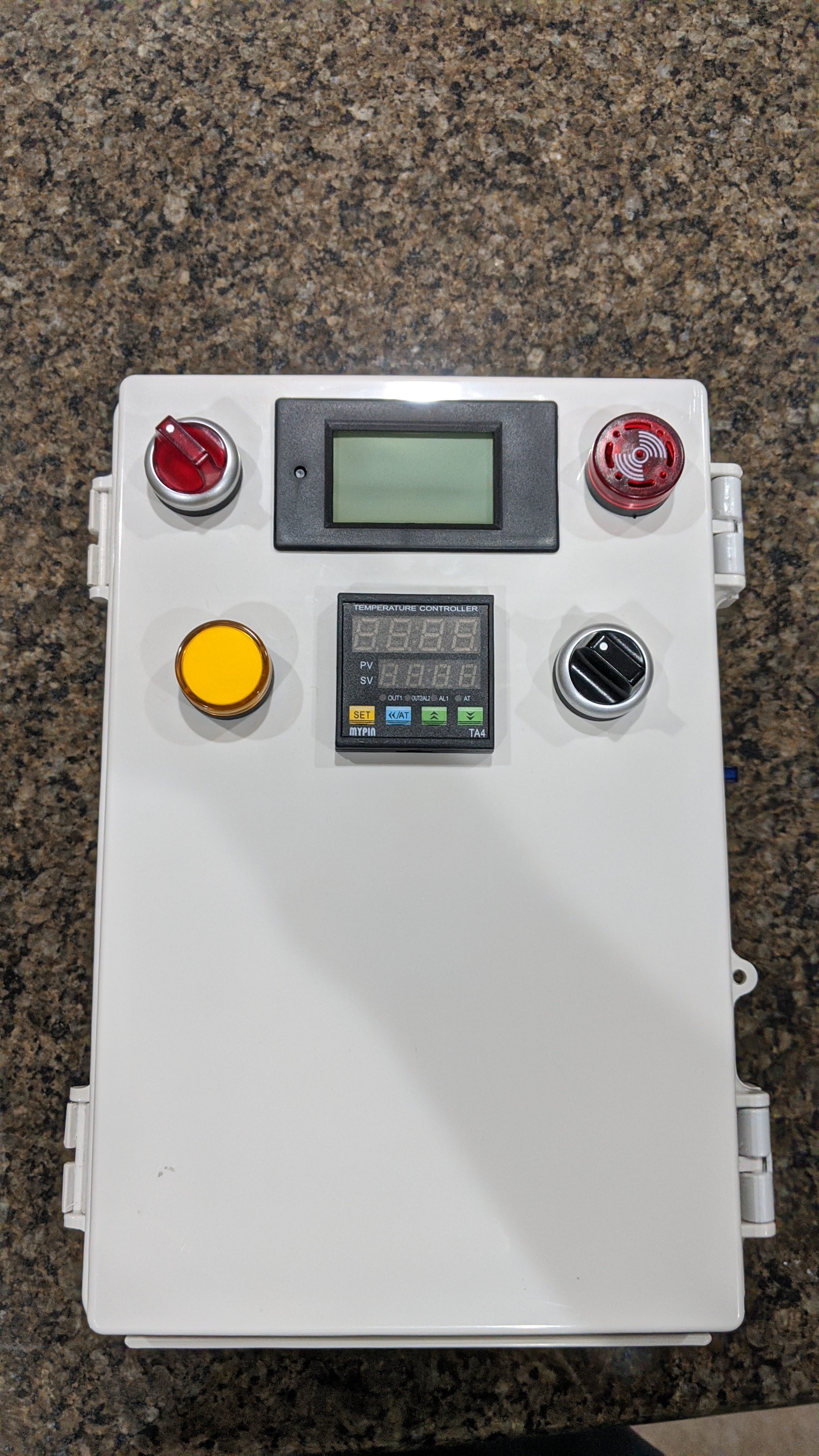
I used doug's schematic and added some bells and whistles. Can switch between 240 and 120. I took this picture before i turned it on and i had the LCD upside down. And then i moved the current meter down to the Line1(red) between the inlet and the contactor so i was accounting for the current being used bu the accessory.

I wish I was better with my cable management. But this is the first step in building my 50+amp automated brewing system.


4181Fij.jpg

QfTVpNF.jpg

RuwpckT.jpg

OG3R8Hx.jpg
 
Looks nice. Recommend you figure out a way to move some air over that SSR and heatsink. Its going to generate a lot of heat. Will extend the life of the SSR.
 
The ssr will get extremely hot but should be ok with that heat sink and a 23a load or smaller. you might want to put a vent in the top though.

I would pick up a better quality ssr to have as a backup though. The foteks are often fake clones and have a very high failure rate compared to all other brands ive ever seen used. I have good louck with the berme branded ones on ebay (like $6-10 shipped) which are made by MGR and also sold under other brand names such as Mager, auberins MGR electric brewing supply and others.

Im guessing that ssr came with the mypin? if so you might be OK but theres many companies all making fakes and clones and using substandard components
 
I'm curious: how are you switching between 120V & 240V when you only appear to have a three wire power input?

Also, can you post the schematic that you used?

Brew on :mug:
 
What is your heating element wattage? That heatsink is good only up to 15Amp if run without a fan. Amd even less if placed in sealed enclosure. I'd add a fan and vent holes.
 
I stand corrected, I thought the heatsink was good for 25amps. Ive used many but I also always used a fan blowing through them.
 
I'm curious: how are you switching between 120V & 240V when you only appear to have a three wire power input?

Also, can you post the schematic that you used?

Brew on :mug:
From the looks of it hes mixed the ground and neutral in the panel. So im guessing no GFCI protecting this setup. it also appears the main contactor does not effect the 120v plugs power.
 
I have the same SSR heatsink combo and you definitely need to change the setup. I cut an opening on the top of the enclosure for the heatsink to stick out into the air and still needed to add a small computer fan to keep it from getting too hot.
 
So i was always concerned about the heat. I was planning on shifting the SSR down a bit and wiring a small fan with vent holes at the top. I didnt realize the heat sink was only rated for 15 amps.... ill reconfigure. I do have the large 40amp heat sink from auberins i can upgrade too. I didnt want to cut that big hole at the top if i didnt have to. Looks like i probably should.

The SSR is a cheapo from amazon, i have a couple. if they start failing i will look for better brands.

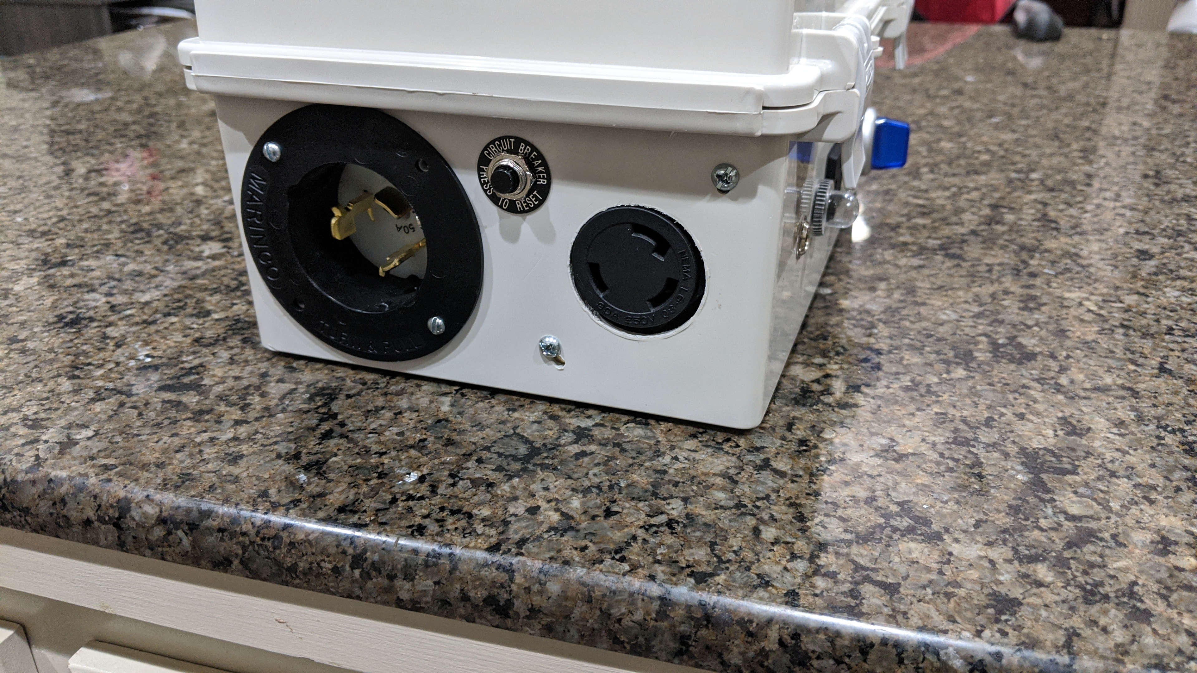
Doug i some what followed your schematic. i used a 30amp relay to swap the Element Line 2 to go either Main Line 2 or Main Neutral. I am using a 4 wire input with a CS6364 plug input. The ground is on the side. I went this route because only wanted to buy 1 main power cable because i am now piecing together a 50 amp automated panel.
dspr120-dv-100-1-pump-1-aux-dual-voltage-input-output-jpg.379978


Yea there is no GFCI within the panel, because i thought my box was GFCI protected...... now that im looking at it...... i think only the 20amp receptacle is GFCI...hhmmmmm might have to get that 100$ gfci breaker. damnit.

Also the main contactor DOES control the 120 outlet i have the 120 outlet wired on the other side of the contacter as doug has shown.

Thanks everyone for the comments. the GFCI is a big one.... i thought it was and never looked back, not i have to look. this is the panel i have and i dont think the 50amp is.

https://www.homedepot.com/p/GE-RV-P...GztOMZyyY_JHUhZPTaRoCCWgQAvD_BwE&gclsrc=aw.ds

"Only the 20a receptacle is GFCI protected"

welp off to find the cheapest way to get GFCI protection
 
I stand corrected, I thought the heatsink was good for 25amps. Ive used many but I also always used a fan blowing through them.

Technically you can use this heatsink when SSR runs on 25Amp but it sets SSR on the edge and its lifespan will be shortened significantly.


Lest dive in some numbers.

Typical 40Amp SSR has a BTA41 triac inside to control a power. It has a 1.2V voltage drop. Considering P= UI we get that on 25 Amp it will generate 25x1.2 =30Watt of heat. And you need to dissipate that heat.


Amount of dissipated heat can be calculated as Ph = (Tsource – Tambient) / Rt Where Rt is a thermal resistance.


Tsource is temperature of heat source. In our case it’s a triac silicon (junction)

Thermal resistance is a sum of Juction to case (Tjc), case to heatsink and heatsink to air resistances - Rt = Rjc + Rch + Rha

According to BTA41 datasheet Tjc is around 0.9 C/W

Typical Rch if you are using thermal grease is round 0.5 C/W

And this particular heatsink has Rha = 2.4 C/W

As a result you have Rt = 0.9 + 0.5 + 2.4 = 3.8 C/W

Now you can calculate triac silicon temperature. Equation is Tj = P * Rt + Tambient

So if you have 30Watt power source and ambient temperature is 25C junction temperature will be T = 30 * 3.8 +25 = 139C

Which is below but very close to maximum allowed junction temperature (150C).

However if you put this heatsink in relatively small un-ventilated box a temperature inside the box can easily raise to 40C or even more. In that case junction temperature will be out of limit. But anyway running silicon close to its limit wiil dramatically shorten it’s lifespan .

To be on safe space you need to keep junction temperature below 100C. It give us P = (100-25) / 3.8 around 20W of dissipated power.

And 20 W / 1.2V gives us around 16Amp if ambient temperature is around 25C.


https://www.wolfautomation.com/media/pdf/heatsinks/carlogavzzi/cg-hfnine-heatsink-datasheet.pdf
https://www.mouser.com/datasheet/2/848/BTA41-600B-1382474.pdf
 
So i was always concerned about the heat. I was planning on shifting the SSR down a bit and wiring a small fan with vent holes at the top. I didnt realize the heat sink was only rated for 15 amps.... ill reconfigure. I do have the large 40amp heat sink from auberins i can upgrade too. I didnt want to cut that big hole at the top if i didnt have to. Looks like i probably should.

The SSR is a cheapo from amazon, i have a couple. if they start failing i will look for better brands.

Doug i some what followed your schematic. i used a 30amp relay to swap the Element Line 2 to go either Main Line 2 or Main Neutral. I am using a 4 wire input with a CS6364 plug input. The ground is on the side. I went this route because only wanted to buy 1 main power cable because i am now piecing together a 50 amp automated panel.
dspr120-dv-100-1-pump-1-aux-dual-voltage-input-output-jpg.379978


Yea there is no GFCI within the panel, because i thought my box was GFCI protected...... now that im looking at it...... i think only the 20amp receptacle is GFCI...hhmmmmm might have to get that 100$ gfci breaker. damnit.

Also the main contactor DOES control the 120 outlet i have the 120 outlet wired on the other side of the contacter as doug has shown.

Thanks everyone for the comments. the GFCI is a big one.... i thought it was and never looked back, not i have to look. this is the panel i have and i dont think the 50amp is.

https://www.homedepot.com/p/GE-RV-P...GztOMZyyY_JHUhZPTaRoCCWgQAvD_BwE&gclsrc=aw.ds

"Only the 20a receptacle is GFCI protected"

welp off to find the cheapest way to get GFCI protection

If I am looking at your pictures and schematic right, it looks like you jammed the neural/white wire for the 120 v side into the ground of the 240 v incoming plug. Correct me if I am wrong.

The schematic shows a 4 wire inlet plug (2 hots, ground and neutral), yours only has 3 (2 hots, and a ground). It will work but is a no no since you will be sending 120 volts down your ground side and out to the 240 v ground side and everything else in between (all grounded components in the box). Grounds are meant to be safety lines that send voltage back to the ground bar in your panel, then to earth if there is a fault. I would consider this wiring setup to be hazardous. If I am missing something, I apologize. Just want to make sure you don't fry something, including yourself.
 
Just pointing out that the MYPIN TA4 has no manual mode. It will control temperature via PID function, but if you will be using this controller to also boil, you must set your temperature at 212F or more.
The MYPIN TD4 has manual function that will allow adjustment of percentage output to the heating element. After placing the controller in manual, you set the output to 100% to get up to boiling. At that point, you can turn down the output to 65% or so to maintain boil.
 
Technically you can use this heatsink when SSR runs on 25Amp but it sets SSR on the edge and its lifespan will be shortened significantly.


Lest dive in some numbers.

Typical 40Amp SSR has a BTA41 triac inside to control a power. It has a 1.2V voltage drop. Considering P= UI we get that on 25 Amp it will generate 25x1.2 =30Watt of heat. And you need to dissipate that heat.


Amount of dissipated heat can be calculated as Ph = (Tsource – Tambient) / Rt Where Rt is a thermal resistance.


Tsource is temperature of heat source. In our case it’s a triac silicon (junction)

Thermal resistance is a sum of Juction to case (Tjc), case to heatsink and heatsink to air resistances - Rt = Rjc + Rch + Rha

According to BTA41 datasheet Tjc is around 0.9 C/W

Typical Rch if you are using thermal grease is round 0.5 C/W

And this particular heatsink has Rha = 2.4 C/W

As a result you have Rt = 0.9 + 0.5 + 2.4 = 3.8 C/W

Now you can calculate triac silicon temperature. Equation is Tj = P * Rt + Tambient

So if you have 30Watt power source and ambient temperature is 25C junction temperature will be T = 30 * 3.8 +25 = 139C

Which is below but very close to maximum allowed junction temperature (150C).

However if you put this heatsink in relatively small un-ventilated box a temperature inside the box can easily raise to 40C or even more. In that case junction temperature will be out of limit. But anyway running silicon close to its limit wiil dramatically shorten it’s lifespan .

To be on safe space you need to keep junction temperature below 100C. It give us P = (100-25) / 3.8 around 20W of dissipated power.

And 20 W / 1.2V gives us around 16Amp if ambient temperature is around 25C.


https://www.wolfautomation.com/media/pdf/heatsinks/carlogavzzi/cg-hfnine-heatsink-datasheet.pdf
https://www.mouser.com/datasheet/2/848/BTA41-600B-1382474.pdf

@brumateur1 knows what he is talking about. His analysis is exactly what electronics manufacturers do. Listen to him.

Brew on :mug:
 
If I am looking at your pictures and schematic right, it looks like you jammed the neural/white wire for the 120 v side into the ground of the 240 v incoming plug. Correct me if I am wrong.

The schematic shows a 4 wire inlet plug (2 hots, ground and neutral), yours only has 3 (2 hots, and a ground). It will work but is a no no since you will be sending 120 volts down your ground side and out to the 240 v ground side and everything else in between (all grounded components in the box). Grounds are meant to be safety lines that send voltage back to the ground bar in your panel, then to earth if there is a fault. I would consider this wiring setup to be hazardous. If I am missing something, I apologize. Just want to make sure you don't fry something, including yourself.
No I appreciate it. But that isn't a L6-30 plugin. It is a locking California style CS 6364. The angle of the pic makes it look like that. The plug has the ground on the side.
 

Attachments

  • IMG_20200206_184433.jpg
    IMG_20200206_184433.jpg
    2.2 MB · Views: 37
  • IMG_20200206_184440.jpg
    IMG_20200206_184440.jpg
    2.3 MB · Views: 35
Just pointing out that the MYPIN TA4 has no manual mode. It will control temperature via PID function, but if you will be using this controller to also boil, you must set your temperature at 212F or more.
The MYPIN TD4 has manual function that will allow adjustment of percentage output to the heating element. After placing the controller in manual, you set the output to 100% to get up to boiling. At that point, you can turn down the output to 65% or so to maintain boil.
You know I realized that this week and I have an ez boil on order. This my pain I had on my shelf from my old sous vide machine I built before the home commercial versions were available.
 
No I appreciate it. But that isn't a L6-30 plugin. It is a locking California style CS 6364. The angle of the pic makes it look like that. The plug has the ground on the side.
OK, just didn't look right at first. Makes sense now.
 
Back
Top