• Please visit and share your knowledge at our sister communities:
  • If you have not, please join our official Homebrewing Facebook Group!

    Homebrewing Facebook Group

Automated Brewery Valve Layout Diagrams

Homebrew Talk

Help Support Homebrew Talk:

This site may earn a commission from merchant affiliate links, including eBay, Amazon, and others.
Thanks. Is the purpose of the orifices purely for flow restriction to get a good flame? The regulator should drop down to the correct delivery pressure and the orifice basically sets the flow? If this is the case, wouldn't I want one orifice per burner and why would you want an orifice at the propane tank?

Correct me if I am wrong. For my low pressure LP system w/ Honeywell control valves, I will need the following (starting at tank and in direction of flow):

(1) LP Tank
(2) Regulator in the 0-30psi range w/ hose
(3) Secondary regulator to the 11"WC range
(4) Isolation valve
(5) Honeywell VR8200 (1 per branch)
(6) Flow Control Valve (1 per branch)
(7) Orifice Connector (1 per branch)
(8) Burner (1 per branch)

Does this seem right?
 
Hey Chris,
Interesting blog! Seems lk you know a lot on breweries.

If so could you help answer few of these questions. Its for a research project.

Q1: How much water is consumed in a brewery every day/every hour?
Q2: What is the inlet / outlet pressure of water (hourly/daily)?
Q3: Do breweries use Pressure Reduction Valves ifor water operations?
Q4: If so, How much are do they reduce pressure by, in feet or PSI?
Q5: What is the entry and exit point of the water?

Would appreciate if you could try and help me out since you know a lot bout breweries!

Thanks!
binson
 
Thanks. Is the purpose of the orifices purely for flow restriction to get a good flame? The regulator should drop down to the correct delivery pressure and the orifice basically sets the flow? If this is the case, wouldn't I want one orifice per burner and why would you want an orifice at the propane tank?

Correct me if I am wrong. For my low pressure LP system w/ Honeywell control valves, I will need the following (starting at tank and in direction of flow):

(1) LP Tank
(2) Regulator in the 0-30psi range w/ hose
(3) Secondary regulator to the 11"WC range
(4) Isolation valve
(5) Honeywell VR8200 (1 per branch)
(6) Flow Control Valve (1 per branch)
(7) Orifice Connector (1 per branch)
(8) Burner (1 per branch)

Does this seem right?


If all burners are low pressure, you only need a low pressure regulator.
Isolation valve?
Items 5 through 8 are correct. (use needle valves)
 
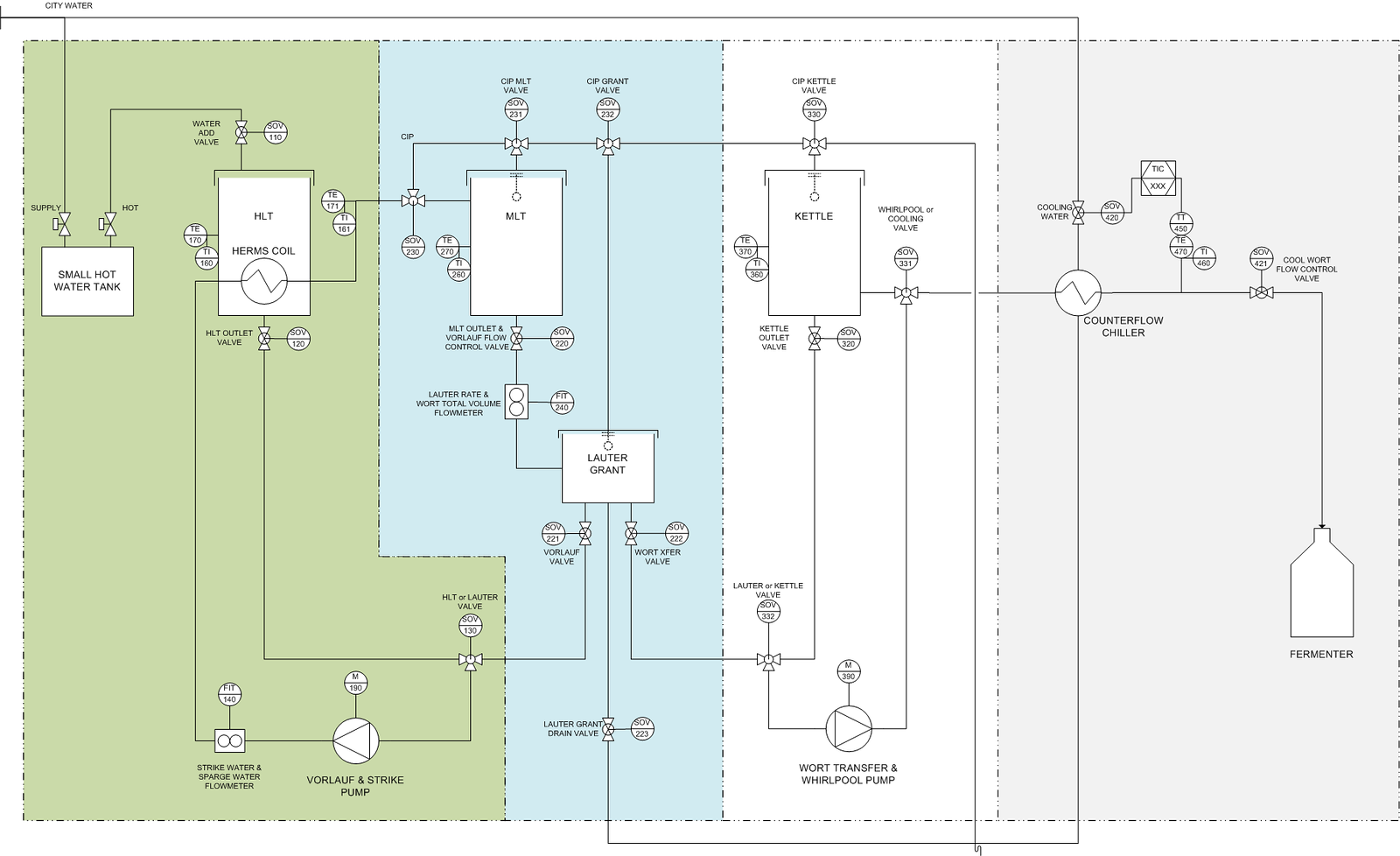
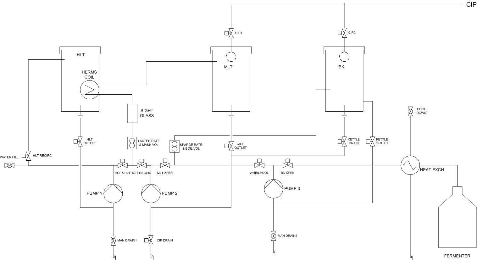
Updated my project, saving one 2 way valve and now being able to properly clean with water both the pumps, the cooler and the herms coil

MyHerms%20V2.001.jpg


Here my project thread.


cheers


gm
 
hmm... looks like someone has controls and instrumentation experience
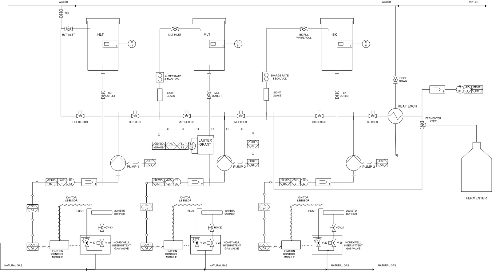
they look just as good as the professional drawings I've worked with
 
So I have 3 little pumps from greatbreweh.com, 2 ifm flowmeters (eBay), couple solenoid valves, and 10 motorized ball valves (eBay).

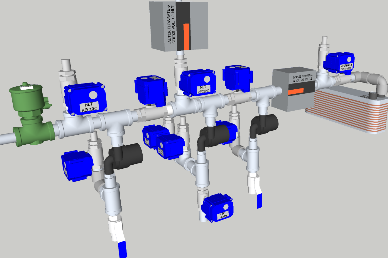
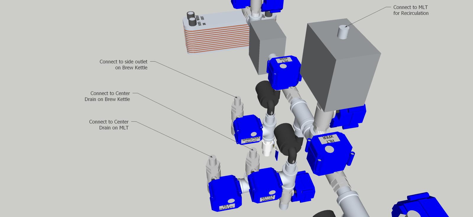
I've been playing around in sketchup a little, I'll modify the P&ID and post it as well later.
MANIFOLD-X3.png


manifoldcallouts2-X3.png


Edit: Here's my napkin-sketch of the process piping to accompany the above piping sketches.

SINGLETIER_plumbingREV3-X3.png


I will be fitting bottom drains on all three vessels, and the Brew Kettle will also have a side drain. This will allow me to whirlpool, and then extract from the side when I pump off the hot wort to the chiller.

I can drain the debris automatically when done. I'm thinking of using a 2" TC on the bottom drains, and then using a 2" x 1" concentric reducer maybe. This should make the bottoms of the kettles drain well.

It's pretty simple, and offers a great deal of flexibility. I am planning an automated CIP cycle that will have it's own vessels and pump etc. The hot PBW or whatever I wash with will pump through sprayballs in the MLT and BK, and return through the CIP drain. Once the vessels are washed, I'll close the CIP drain and capture a volume of the hot wash solution and do an automated line wash which will flush all the wort lines with hot wash solution. Open the drain back up, let the CIP balls run for a little longer to re-flush the kettles, then automatic rinse cycle using the same idea and optionally.

I may use a second CIP tank with StarSan to circulate through the system after the rinse. It would also allow me to run a StarSan cycle before starting to brew.

I put some manual ball valves at the other two lowest points of the plumbing, so when clean it can all be drained.

Comments?
 
A few more design notes:

I neglected to mention that since these little pumps are 12VDC, I'll be using a speed control from my controller to manage the lauter rate and sparge rate.

The motorized ball valves have about a 2.5 second OPEN or CLS time, so it would be possible to manage flow rates by partially opening or closing the valves and leaving the pump run full tilt.

The flowmeters I bought from eBay for about $90 ea. and are stainless wetted parts ultrasonic units that will provide a pulse output, or analog output. The analog output can alternately be configured for temperature. I might use the pulse output for flow, and use the temperature output on the analog so I don't have to mount temperature sensors in the piping or on the MLT or BK.

The HLT and BK will be heated my 4500W heating elements, driven by SCRs. I might look at getting a Phase Control SCR for the BK which would allow more precise heat control.

I had thought about putting a heating element right in the MLT and have the false bottom up higher. This would eliminate the herms coil in the HLT. Not sure on that yet.

I have a couple of stainless float switches for the HLT and BK.

3 for the HLT
  1. High Level - Initial Fill Level for Strike and hopefull enough left for Sparge
  2. Low Level - Protect the Heating Element
  3. Herms Min Level - Enough Water for Sparge and cover the herms coil

And just the one low level switch on the BK to protect the element.

I've written some code on my Arduino mega just for fun, cool little controller, but have a Linux/Android controller board in mind for the final version. It has an HDMI output, so I'll use a little 7" touchscreen with it. It should be here soon.

Hmm, maybe I should have started a build thread...
 
warehouse brewery and blackheart brewery- how did you go about making those awesome control panel faces? i saw the link on warehousebrewerys website but I'm not a designer so it looks a little intimidating.
 
Back
Top